5
For Warranty Service Call: 833-474-0367 Range Owner’s Manual 20201109
9. There must be adequate clearance for removal of the front panel. All major parts except the
burners are removable through the front if the gas is disconnected.
10. A manual gas valve should be installed upstream of the device where is easy to reach to shut
off the fuel supply to the range in the event of an emergency.
11. It may be necessary to adjust the balance of gas volume and air supply to each burner. This
must be done by an authorized service technician.
12. Pipe threading compound must be resistant to the action of liquefied petroleum gas. DO NOT
USE TEFLON TAPE.
The installation of this appliance must conform to local codes, or in the absence of local
codes, the National Fuel Gas Code, ANSI Z223.1/NFPA 54, or the Natural Gas and Propane
Installation Code, CSA B149.1, as applicable.
• The appliance and its individual shut off valve must be disconnected from the gas supply
piping system during any pressure testing of that system at test pressures in excess of ½ PSI
(3.5kPa).
• The appliance must be isolated from the gas supply piping system by closing its individual
manual shut off valve during any pressure testing of the gas supply piping system at test
pressures equal to less than ½ PSI (3.5kPa).
Gas Piping: Gas piping shall be of such size and so installed as to provide a supply of gas sufficient
to meet the full gas input of the appliance. If the
appliance is to be connected to existing piping, it
should be checked to determine if it has adequate
capacity. Joint compound (pipe dope) should be
used sparingly and only on the male threads of the
pipe joints. Such compounds must be resistant to the
action of Liquefied Propane (LP) gases.
Regulator information: ¾” NPT (National Pipe
Thread) inlet and outlet; factory adjusted for five (4”)
inch Water Column (WC) Natural Gas standard and may be converted by qualified personnel to be
used for Propane at ten (10”) Water Column pressure.
Prior to connecting the regulator, check the incoming line pressure. The regulator can only withstand
a maximum pressure of ½ PSI (14” WC). If the line pressure is beyond this limit, a step-down
regulator before the regulator provided will be required. The arrow forged into the bottom of the
regulator body shows gas flow direction and should point downstream to the appliance.
CAUTION: Any loose dirt or metal particles, which can enter the gas line on this appliance, will
damage the valve and affect its operation. When installing this appliance, all pipe and fittings must be
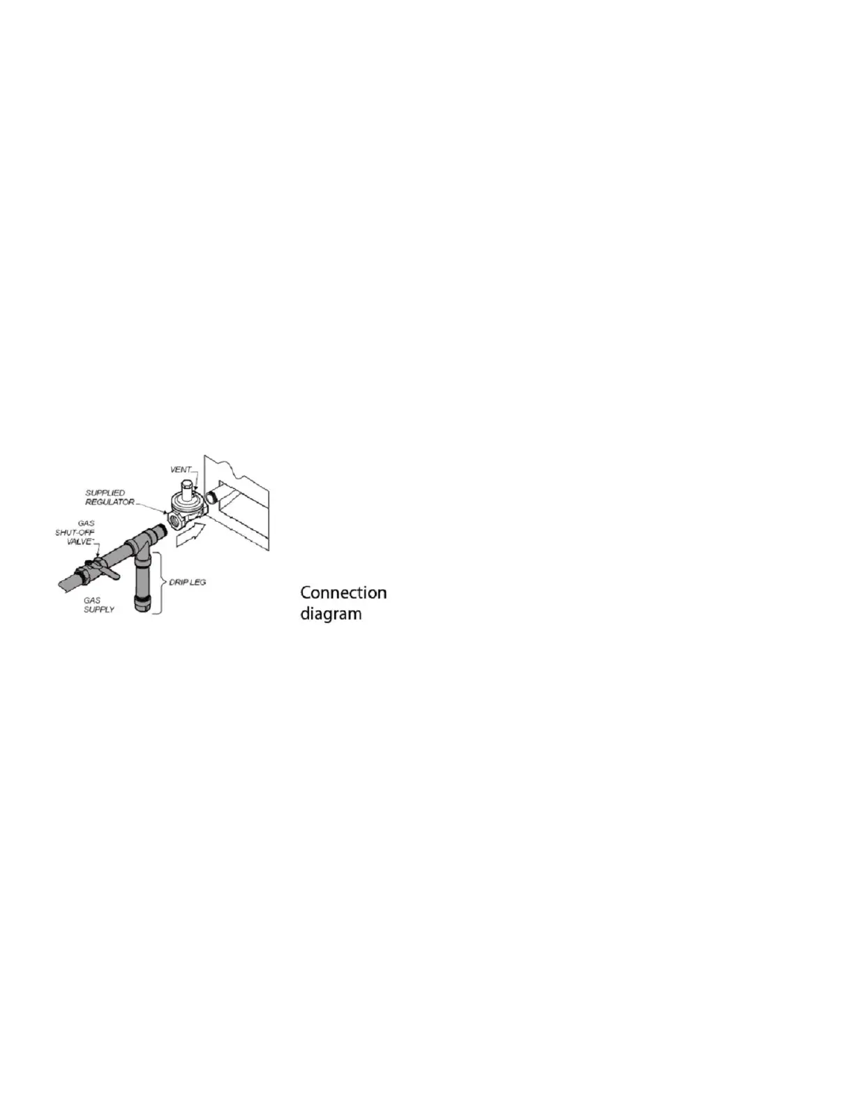
free from any internal contaminates. It is recommended that a “drip leg” be installed in-line before the
regulator. See diagram above.
Manual Shut Off Valve: A manual shut off valve should be installed upstream from the manifold,
within four (4) feet, (1.2M) of the appliance and in a position where it can be reached in the event of
an emergency.
 Loading...