70258-a.11-HELIO A7 USER MANUAL PLUS
19
User
Manual
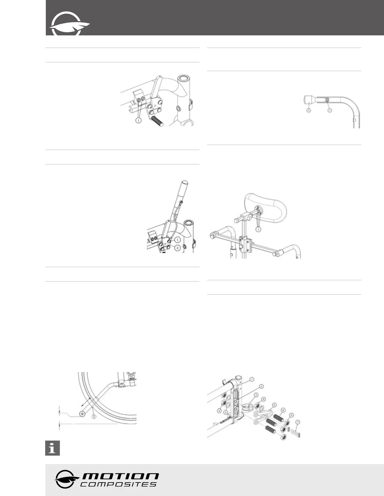
10.12 Wheel Locks
10.12.1 Replacing/Adjusting the wheel lock
• Loosen screws (1) (Fig. 38).
• Slide the wheel lock to the
desired position.
• Tighten screws (1) to a snug
fit. Final tightening should be
done manually.
• Once engaged, the wheel
lock should embed 3 mm into
the tire.
Fig. 38
10.13 Lock Extension
10.13.1 Replacing/Adjusting the wheel lock
extensions
• Loosen screw (1) (Fig. 39).
• Align eyelet (2) with the mounting hole.
• Re-tighten screw (1) on the lock lever.
Fig. 39
10.14 Anti-tippers
10.14.1 Adjusting the Height of the Anti-tippers
Anti-tippers MUST be used with your wheelchair at all times.
Because anti-tippers are an option in some markets on this
wheelchair, Motion Composites strongly recommends to order
the anti-tippers as they are an important safeguard for the
wheelchair user. Always use anti-tippers.
The anti-tippers should be between 1½ and 2 ¾ inches (40
to 70 mm) off the ground. Improper spacing may result in
wheelchair hang ups over obstacles or not preventing the
wheelchair from tipping.
• Press the push-button (1) (Fig. 40) and slide anti-tippers
extensions to desired length.
• Ensure the button snaps back into place.
Fig. 40
If you are unable to adjust the anti-tippers to the proper
height, contact your Motion Composites dealer to
replace your anti-tipper for another size.
10.15. Headrest Kit and
Headrest Support
10.15.1 Installing a headrest support
• Cut the end of the push-handle with
a knife in order to be able to see the
inside of the push handle.
• Insert a 1/4”-20 grip nut (1) (Fig. 41)
with the grip nut insertion tool (2)
inside the handle (40 mm).
• Install fastening device of the
headrest support by tightening it in
the 1/4”-20 roll pin.
Fig. 41
10.15.2 Installing Headrest Kit
• Once the headrest support is installed, insert the adjustable
headrest into the horizontal receiver.
• Install headrest on the ball pivot and tighten the three screws
(1) (Fig. 42).
• Once the adjustment is completed, firmly tighten all parts.
Fig. 42
10.16 Amputee Axle Plate
10.16.1 Installing an amputee axle plate
• Install mounting plate (1) (Fig. 43) by closing the clamps
around the frame.
• Insert a second axle receiver (2) on the axle plate
• Install the back clamp (3) onto the rear of the frame.
• Insert two axle bushing (8) through axle plate (6) and in the
two axle receiver (2) and secure with bolt and washer (4)(5).
• Insert two screws (7) into amputee axle plate through the
mounting clamp and tighten.
• Insert axle bushing (8) through the amputee plate and tighten
nuts (9).
Fig. 43
 Loading...