T (450) 588-6555 - 1 866 650-6555 F (450) 588-0200
info@motioncomposites.com
16
If you ignore these Warnings or fail to inspect or maintain your wheel-
chair as directed in the manual, you may fall, tip over or lose control
of the wheelchair and seriously injure yourself or others or damage
the wheelchair
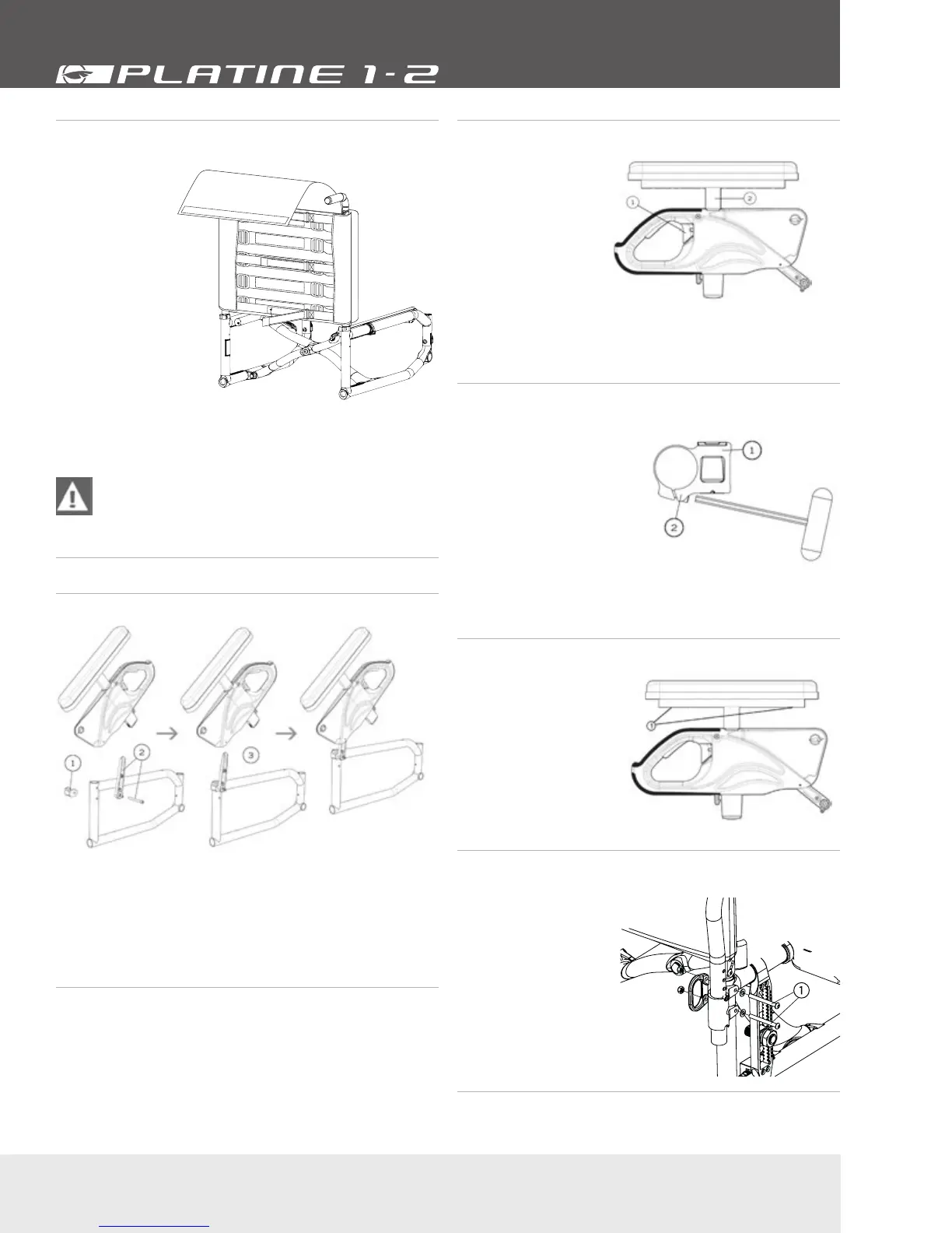
10.5.6 Installing/Removing Adjustable Tension
Back Upholstery
• To remove the
adjustable Tension
Back Upholstery,
use the same
steps as the
standard back
upholstery. Lift
the back cover
to have access
to the 2 bolts
to remove the
upholstery.
• To adjust the
tension, first lift
the back-cover
flap to expose the
horizontal straps
(a). Release the
Velcro straps,
then adjust each strap individually using the Velcro or the
buckle tension adjustment system to the desired tension.
Fig. 16a
ATTENTION – AVOID over-tightening of the strap
assembly as this may cause damage to the integrity of
the back canes. Lastly, fold down the back-cover flap
over the horizontal adjustment straps to complete your
adjustment.
10.6 Armrest
10.6.1 Installing Flip-back Armrests
Fig. 14a Fig. 14b
Fig. 14c
• Insert the flip-back pivot (1, 2) (Fig. 14a) and screw it in place,
making sure it stays in place but can rotate easily.
• Insert the armrest (Fig. 14b) on the flip-back pivot than rotate
it until it clicks with the armrest receiver (Fig. 14c) (for clamp
installation, see 10.6.3 installing removable T-armrests).
10.6.2 Adjusting the height of Flip-back and T
armrests
• Flip lever (1) (Fig. 15)
left or right to unlock
the armrest.
• To adjust height, slide
the upper part of the
armrest into the lower
part.
• Adjust the structure (2)
at the desired height.
• Flip the lever back to
the closed position.
• Make sure the armrest clicks in place for complete
securement.
Fig. 15
10.6.3 Installing removable T-armrests and rigid
sideguard
• Install armrest receiver (1)
(Fig. 19) on the upper tube
of the frame at a distance
of 160mm (6 1/4”) from the
rear tube of the frame.
• Slightly tighten screws (2) to
allow the clamp to rotate.
• Insert armrest or sideguard
into receiver (1).
• Rotate receiver (1) until the
sideguard is perpendicular to
the seat.
• Tighten screws (2) firmly.
Fig. 19
10.6.4 Replacing Armrest Pad
• Remove screws (1) (Fig.
20) located under pad
(through the tube).
• Replace with new
armrest pad.
• Reinstall screws (1) and
tighten firmly.
Fig. 20
10.6.5 Installing the Swing-away Armrest
receiver
• Remove the two bolts (1)
(Fig. 21).
• Align the armrest
receiver with the
mounting holes of the
frame and of the transit
securement anchor.
• Reinstall the bolts and
tighten firmly.
Fig.
22
 Loading...