T (450) 588-6555 - 1 866 650-6555 F (450) 588-0200
info@motioncomposites.com
20
If you ignore these Warnings or fail to inspect or maintain your wheel-
chair as directed in the manual, you may fall, tip over or lose control
of the wheelchair and seriously injure yourself or others or damage
the wheelchair
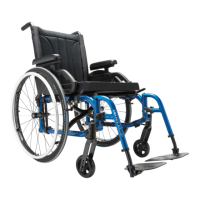
10.11.4 Adjusting rear wheel spacing
Fig.
36
• The rear wheels can be adjusted laterally
by repositioning axle bushing (1) (Fig. 36) on
mounting plate (2).
• Loosen nuts (3) on the axle bushing (1).
• Turn the bushing (1) in the desired direction
to adjust the spacing.
• Firmly tighten the nuts (3).
10.12 Wheel Locks
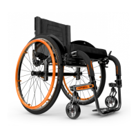
10.12.1 Replacing/Adjusting the Wheel Locks
1
• Loosen screws (1) (Fig. 27).
• Slide the wheel lock to the desired
position.
• Tighten screws (1) to a snug fit. Final
tightening should be done manually.
• Once engaged, the wheel lock should
embed 1/8 “ (3 mm) into the tire.
Fig. 27
10.13 Lock Extensions
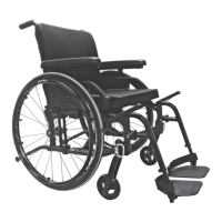
10.13.1 Replacing/Adjusting the wheel lock
extensions
1
• Loosen screw (1) (Fig. 28).
• Align eyelet with the mounting hole.
• Re-tighten screw (1) on the Lock lever.
Fig. 28
10.14 Anti-tippers
10.14.1 Adjusting the Height of the Anti-tippers
Fig. 29
Anti-tippers MUST be
used with your wheelchair
at all times. Because
anti-tippers are an option
in some markets on
this wheelchair, Motion
Composites strongly
recommends to order the
anti-tippers as they are
an important safeguard
for the wheelchair user.
Always use anti-tippers.
The anti-tippers should be between 1½ and 2 ¾ inches (40
to 70 mm) off the ground. Improper spacing may result in
wheelchair hang ups over obstacles or not preventing the
wheelchair from tipping..
• Press the push-button (1) (Fig. 29) and slide anti-tippers
extensions to desired length.
• Ensure the button snaps back into place.
If you are unable to adjust the anti-tippers to the proper
height, contact your Motion Composites dealer to
replace your anti-tipper for another size.
10.15. Headrest Kit and
Headrest Support
10.15.1 Installing a headrest support
• Cut the end of the push-handle with
a knife in order to be able to see the
inside of the push handle.
• Insert a 1/4”-20 grip nut (1) (Fig. 41)
with the grip nut insertion tool (2)
inside the handle (40 mm).
• Install fastening device of the
headrest support by tightening it in
the 1/4”-20 roll pin.
Fig. 41
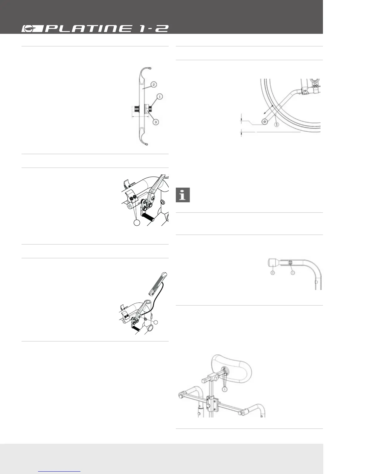
10.15.2 Installing Headrest Kit
• Once the headrest support is installed, insert the adjustable
headrest into the horizontal receiver.
• Install headrest on the ball pivot and tighten the three screws
(1) (Fig. 42).
• Once the adjustment is completed, firmly tighten all parts.
Fig. 42
 Loading...