EasyManua.ls Logo

MotionGrey Ergo 2 Series User Manual

MotionGrey Ergo 2 Series
2 pages
To Next Page IconTo Next Page
Page #1 background imageLoading...
Page #1 background image
x1x6
B
C*2
STEP 2
S3x3
S3x3
x1x1
E
F
D
E
F
E
F
STEP 3
Make sure the Front labels are in the same direction.
x1x2
STEP 1
A*2
S3x2
B
Assembly Instruction
Ergo 2 Series 43" x 24"
Scan to access the step-by-step
installation instructions and video.
SCREW ACCESSORIES
6mm Allen Key x1
3mm Allen Key x1
Bracket Screw
(M8)
x12
Metal Rod Connector
Screw (M5)
x2
Frame Screw
(M4)
x2
Foot Base & Motor
Screw (M8)
x9
Footer x4
Wire Clip x3
Wood Screw
(M4)
x30
S1 S2 S3 S4 S5
S7
S8 S9
S6
PARTS ACCESSORIES
Frame x2
Central Bracket x2
Metal Frame Connector x2
Motor x1
Metal Rod #1 x1
Metal Rod
Connector x1
Metal Rod #2 x1
Cable Clip x1Power Cord x1Cup Holder x1
Headphone Hook x1
Side Bracket x2Foot Base x2
Keypad x1
Table Top x1
A B C D
E
F
G
H I
J
K L M N O
Question and Answer IconNeed help?

Do you have a question about the MotionGrey Ergo 2 Series and is the answer not in the manual?

MotionGrey Ergo 2 Series Specifications

General IconGeneral
BrandMotionGrey
ModelErgo 2 Series
CategoryIndoor Furnishing
LanguageEnglish

Summary

Assembly Step 1: Base Frame Construction

Connecting Frame Parts

Assemble the main frame using parts A, B and screws S3, S1, ensuring front labels align.

Assembly Step 2: Leg and Motor Attachment

Attaching Legs to Frame

Connect leg components (B, C) to the frame using screws S3, ensuring correct alignment.

Assembly Step 3: Final Leg Securing

Securing Legs to Base

Attach leg parts (E, D, F) to the frame and foot bases using screws S6 and S1.

Assembly Step 4: Connecting Rod Installation

Installing Metal Rods

Attach metal rods (G) to the frame assembly using screws S4 and S2.

Assembly Step 5: Motor and Control Box Mounting

Mounting Motors and Box

Install motors (E) and control box (I) onto the frame using screws S3, S5, S2, S1.

Assembly Step 6: Leg Alignment and Fastening

Aligning and Tightening Legs

Ensure leg parts (H) are vertical and tighten screws S6, S8.

Assembly Step 7: Tabletop Attachment

Securing Tabletop

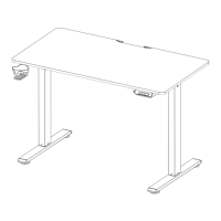
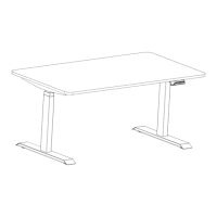
Mount the tabletop (J) to the assembled frame using screws S9 and S1.

Assembly Step 8: Electrical Connections

Connecting Electronics

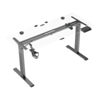
Connect keypad (K), hook (L), holder (M), and power cord (N) using screws S9, S7.

Assembly Step 9: Final Setup and Operation

Initial Power On

Perform final checks and press the RST key to start the assembled desk.

Related product manuals