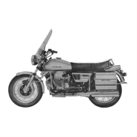
Do you have a question about the MOTO GUZZI CALIFORNIA 1100i and is the answer not in the manual?
| Displacement | 1064 cc |
|---|---|
| Bore x Stroke | 92 mm x 80 mm |
| Transmission | 5-speed |
| Final Drive | Shaft |
| Front Suspension | Telescopic fork |
| Front Brakes | Dual disc |
| Rear Brakes | Single disc |
| Seat Height | 780 mm |
| Horsepower | 72 hp |
| Fuel System | Electronic Fuel Injection |
| Rear Suspension | Dual shocks |
| Engine Type | Air-cooled, 90-degree V-twin |
Details of the front wheel assembly, including rim size and spoke information.
Details of the rear wheel assembly, including rim size and spoke information.
Recommended tyre pressures for front and rear wheels based on load.
Diagrams and description of the front and rear hydraulic brake systems.
Description and diagram of the Ducati alternator and regulator unit.
General characteristics and specifications for the Valeo starter motor.
Details on the Magneti Marelli Digiplex electronic ignition system for carburettor versions.
Recommended types of spark plugs and electrode gap specifications.
Legend for the electrical wiring diagram for carburettor versions.
Legend for the electrical wiring diagram for electronic injection versions.
Overview of the instrument panel, including key switch and warning lights.
Location and operation of the handlebar light switches.
Detailed specifications and diagrams for inlet and exhaust valves and guides.
Specifications and measurement procedures for engine cylinders.
Specifications and measurement procedures for pistons for different models.
Instructions and specifications for mounting connecting rods to the crankshaft.
Procedures for checking and balancing crankshaft weight with connecting rods.
Data for valve timing, including opening and closing points and clearances.
Inspections and controls for the engine oil delivery pump.
Setting data and adjustment procedures for the Dell'Orto carburettor version.
Information regarding the electronic injection system and potentiometer regulation.
Instructions for adjusting spring pre-loading and damper operation on front forks.
Procedure for changing the hydraulic fluid in the front fork legs.
