Do you have a question about the MOTO GUZZI V11 LE MANS MY 2003 and is the answer not in the manual?
| Displacement | 1064 cc |
|---|---|
| Compression Ratio | 9.8:1 |
| Fuel System | Electronic Fuel Injection |
| Transmission | 6-speed |
| Final Drive | Shaft |
| Front Tire | 120/70 ZR17 |
| Rear Tire | 180/55 ZR17 |
| Bore x Stroke | 92 mm x 80 mm |
| Rear Suspension | Single shock, adjustable preload |
| Front Brakes | Dual 320 mm discs |
| Rear Brakes | Single 282 mm disc |
| Wheelbase | 1490 mm |
| Seat Height | 800 mm |
| Engine Type | V-twin, 90° |
| Max Power | 91 hp (67 kW) @ 7800 rpm |
| Frame | Tubular steel |
| Fuel Capacity | 22 liters (5.8 US gal) |
Essential safety rules and regulations for operating and maintaining the motorcycle.
Guidelines and rules to follow for performing maintenance procedures.
Details for identifying the motorcycle, including chassis and engine numbers.
Specifications for lubricants and fluid capacities for refilling various systems.
Detailed technical specifications of the motorcycle's engine, chassis, and components.
Specified torque values for various bolts and fasteners during assembly and maintenance.
Pre-operation checks and tests to ensure the motorcycle is safe and ready for use.
Information on the engine ignition system and its operation.
Motorcycle parking instructions.
Description of system operation during the acceleration stage.
A table outlining scheduled maintenance tasks based on mileage intervals.
Information specific to the front wheel of the motorcycle.
Information specific to the rear wheel of the motorcycle.
Details and procedures for the front hydraulic brake system.
Details and procedures for the rear hydraulic brake system.
Information and procedures related to the front fork assembly.
Information on the rear shock absorber and its maintenance.
Details about the steering shock absorber and its adjustment.
Tire specifications for the front and rear wheels, including brands and sizes.
Information related to the motorcycle's steering system.
Details concerning the half-handlebars on these variants.
Details on the front and rear suspension systems.
Details of the front and rear brake systems, including disc size and caliper type.
Overview of the motorcycle's fuel system components and function.
Overview of the motorcycle's fuel system components.
Specific information about the fuel tank, labeled as '3'.
Details on the electric fuel pump unit, labeled as '1'.
Information about the fuel filter, labeled as '2'.
Details on the electro-injectors, labeled as '3'.
Information on the pressure adjuster, labeled as '4'.
Procedures for removing and installing the air filter box, labeled as '1'.
Information on the throttle body, labeled as '2'.
Description of the intake air circuit, including filter, manifold, and throttle body.
Overview of the exhaust system's features and design.
Information about the exhaust pipes.
Procedures for removing and checking the expansion chamber and lambda sensor.
General guidelines and precautions for engine overhaul procedures.
Step-by-step instructions for removing and installing the engine unit.
Explanation of the engine's lubrication system and its components.
Details on the cylinder heads and the engine's timing system.
Information regarding the cylinders and pistons of the engine.
Details about the motorcycle's clutch system.
Information on the alternator and its function.
Details concerning the crankshaft and connecting rods of the engine.
Overview of the primary features of the gearbox.
Procedures for removing and installing the gearbox.
Step-by-step instructions for disassembling the gearbox.
Procedures for reassembling the gearbox after disassembly.
Information about the rear transmission housing.
Details regarding the transmission shaft.
General overview of the motorcycle's electrical system and its components.
Information and maintenance for the motorcycle's battery.
Details about the starter motor and its operation.
Description of lights, acoustic signals, dashboard, and controls.
Information on the side stand switch.
Location and description of the fuse terminal board.
Details on the alternator and voltage controller.
Motorcycle identification data for various models.
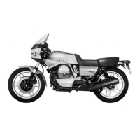
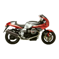
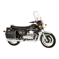
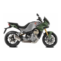
Technical specifications specific to Naked and Le Mans variants.
Procedure for adjusting the headlight beam on Le Mans models.
Instructions for cleaning the motorcycle's windscreen.
Maintenance schedule table for Naked and Le Mans variants.
Information and procedure for replacing the fuel filter.
Details regarding the wing mirrors on Le Mans models.
Information about the rear fairing.
Details concerning the fairing on Le Mans models.
Procedure for removing and installing the clear plate of the headlight fairing on Le Mans models.
Details about the steering shock absorber on Le Mans models.
Details concerning the half-handlebars on these variants.
Procedures for engine unit removal and installation on these variants.
Information about dashboard warning lights on Le Mans models.
Motorcycle identification data for various models.
Specifications for lubricants and refilling procedures for various models.
Detailed specifications for various motorcycle models.
Pre-operation checks and tests for various models.
Information on engine ignition for various models.
Motorcycle parking instructions for various models.
Details on the Öhlins steering damper for V11 Cafe Sport.
Procedure for adjusting the headlight beam on V11 Cafe Sport and Ballabio.
Information and procedures related to the front fork assembly.
Detailed parts list for the Marzocchi front fork assembly.
Procedures for removing Marzocchi and Öhlins 2nd series front forks.
Procedures for reassembling Marzocchi and Öhlins 2nd series front forks.
Procedures for removing stanchions and sliders from Marzocchi and Öhlins forks.
Procedure for changing the oil in Marzocchi front forks.
Procedure for changing fork oil and dust seals on Öhlins forks.
Procedure for changing the oil in Öhlins front forks.
Procedure for filling the front fork with Öhlins oil.
Procedures for disassembling components related to carburation control.
Procedures for reassembling components after carburation adjustments.
Important note regarding the installation of the roll-over shut-off valve.
Overview of the exhaust system's specifications.
Details about the exhaust and balance pipes.
Procedures for removing and checking the expansion chamber and lambda sensor.
Procedure for checking the correct operation of the lambda sensor.
Procedures for reassembling and fitting the pre-selector cover.
General overview of the electrical system and its components.
Location and description of the fuse terminal board.
Wiring diagram for the non-catalytic version of the electrical system.
Note regarding the removal of headlight and instrument panel.
Procedures for replacing damaged fuses, including safety precautions.
Procedures for checking the regulator for defects using workshop tools.