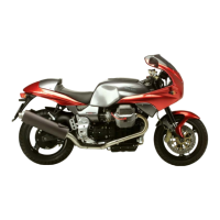
Do you have a question about the MOTO GUZZI V11 SPORT MY 2003 and is the answer not in the manual?
| Brand | MOTO GUZZI |
|---|---|
| Model | V11 SPORT MY 2003 |
| Category | Motorcycle |
| Language | English |
General safety rules for operating and maintaining the motorcycle.
Detailed technical data for the motorcycle models.
Essential checks to perform before starting the engine.
Operation and adjustment of hydraulic clutch and front brake controls.
Information on the steering system, head, and components.
Detailed procedures for removing and installing the engine unit.
Overview of the motorcycle's electrical system components and layout.
Information on vehicle identification number (VIN) structure and location.
Detailed technical data for V11 Sport Naked and Le Mans variants.
Steps for removing and installing the gearbox assembly.
Maintenance schedule table outlining tasks at different mileage intervals.
Details about the vehicle identification number and its components.
Maintenance schedule table covering various procedures and intervals.
Detailed technical specifications including engine, timing, fuel, exhaust, lubrication, and ignition.
Specific details about the engine configuration, bore, stroke, and performance.
Information on the clutch, primary drive, gearbox, and secondary drive systems.
Details on the gearbox, including gear ratios and engagement type.
Adjustment procedure for Marzocchi front forks.
Description of the rear steel swing arm and Sachs Boge shock absorber.
Description of the front Brembo double disc brake system.
Details of the rear fixed disc brake system with double cylinder caliper.
Key physical dimensions and weight specifications for the motorcycle.
Steps for adjusting the headlight vertical beam for proper aim and visibility.
Advice on cleaning the windscreen, including precautions and recommended materials.
Explanation of maintenance symbols (A, C, R) and key notes for the service schedule.
Step-by-step guide for removing, replacing, and refitting the fuel filter.
Instructions for removing and reinstalling the wing mirrors on Le Mans models.
Steps to remove and reinstall the rear fairing and tail guard.
Instructions for removing and reinstalling the fairing on Le Mans models.
Steps for removing and reinstalling the clear plate of the headlight fairing.
Procedures for removing, adjusting, and reinstalling the steering shock absorber.
Steps to remove and reassemble the steering head unit and related components.
Steps for removing and reinstalling RH handlebar controls and components.
Steps for removing and reinstalling LH handlebar controls and components.
Procedures for removing and reinstalling the fuel electric pump unit.
Detailed steps for removing the engine unit from the motorbike.
Steps for reinstalling the engine unit onto the motorbike.
Instructions for removing and refitting the headlight on Le Mans models.
Steps for replacing headlight bulbs.
Procedures for removing, refitting, and replacing front direction indicator bulbs.
Steps for replacing dashboard warning light bulbs.
Instructions for replacing fuses, including precautions and fault tracing.
Legend for electrical system diagram components, wiring, and fuses.
Steps for removing and reinstalling the fuel electric pump unit.
Steps for starting a cold engine, including choke usage and warnings.
Steps for starting a warm engine, noting differences from cold start.
Instructions for parking light usage and key switch operation.
Details on steering damper function, adjustment, and settings.
Steps for adjusting headlight beam for proper aim and visibility.
Steps for adjusting Marzocchi fork settings, including warnings.
Steps for adjusting Öhlins telescopic fork settings, including factory values and warnings.
Steps for adjusting Öhlins rear monoshock settings, including lubrication and warnings.
Explanation of maintenance symbols (A, C, R) and key notes for the service schedule.
Steps for removing and reinstalling the front fairing for specific frame numbers.
Details on different fork types (Marzocchi, Öhlins) and associated models.
Steps for removing and reassembling Marzocchi and Öhlins 2nd series forks.
Steps for removing and reassembling Öhlins 1st series forks.
Diagram and list of parts for the Marzocchi front fork.
Diagram and list of parts for the Marzocchi front fork.
Steps for removing and reassembling fork stanchions and sliders.
Steps for installing fork stanchions and sliders, with warnings.
List of special tools and their applications for Öhlins front fork service.
Instructions for changing Marzocchi front fork oil, including frequency and reference.
Detailed steps for changing Öhlins front fork oil, including tool usage and warnings.
Steps for filling Öhlins front fork with oil, including oil level and tool usage.
Steps for changing Öhlins fork oil and dust seals, including tool requirements.
Instructions for replacing fuses, including precautions and fault tracing.
Overview of the electrical system components, including lights.
Power ratings for headlight and taillight components.
Note on removing headlight and instrument panel, requiring prior fairing removal.
Steps for replacing fuses and precautions to avoid damage or fire.
Procedures for checking the regulator and identifying defects, with warnings.
Lists components of the fuel circuit including tank, pump, filter, injectors.
Details the fuel injection process and components, referencing fuel pump assembly.
Steps for removing and reinstalling the fuel tank, with safety warnings.
Procedures for removing and reinstalling the fuel electric pump unit.
Describes the air intake circuit including filter box, manifold, and throttle body.
Details of the air filter box and its removal/installation.
Steps for removing and reinstalling the air filter box.
Steps for removing and reinstalling the throttle body, with lubrication advice.
Overview of the electrical circuit's function and list of its components.
How the ECU manages engine timing, fuel, and ignition in normal conditions.
How the ECU manages engine start-up, including fuel pump activation and initial control.
How the system manages fuel during acceleration and safety precautions.
Guidelines for safely and correctly operating the AXONE 2000 diagnostic tool.
How to navigate the AXONE2000 main menu and select functions.
Explanation of the auto-diagnostics function for connecting to ECUs.
Describes interface modules for connecting AXONE2000 to vehicle systems.
Information on the memory card and its insertion into the read/write unit.
How to power the AXONE2000 using internal battery or external cable.
Steps for replacing the AXONE2000 battery, including access and warnings.

