Do you have a question about the Motomaster 011-2038-4 and is the answer not in the manual?
Details about AC output voltage, input, and maximum power ratings.
Specifications for USB output, efficiency, and voltage shutdown thresholds.
Information on operating temperature range, dimensions, and weight of the inverter.
Guidance on calculating the total wattage of devices to avoid overloading the inverter.
Instructions for connecting the power inverter to a power source.
Steps for powering the inverter on and off.
Instructions for utilizing the USB charging port.
Details on built-in safety features and their indicators.
Instructions for replacing the fuse in the 12 V outlet plug.
Diagnosing and resolving issues related to low battery voltage.
Troubleshooting high voltage shutdowns and battery system issues.
Resolving issues caused by connecting devices with excessive power ratings.
Addressing shutdowns due to overheating and ensuring proper ventilation.
Diagnosing why connected devices may not power on.
Troubleshooting issues with the inverter only running small loads.
Identifying causes and solutions for low power inverter output.
Addressing issues leading to unexpectedly short battery run times.
Troubleshooting steps when the power inverter does not provide power.
Solutions for minimizing television signal interference.
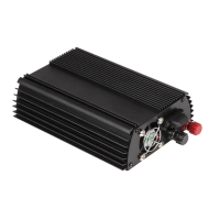
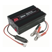
The MotoMaster 400 W 12 V/24 V Power Inverter is an electronic device designed to convert low-voltage direct current (DC) from a battery into conventional 115 V alternating current (AC), similar to household power. This allows users to operate standard household devices in 12 V vehicles, 24 V trucks, boats, and RVs. The inverter utilizes a modified sine wave to deliver consistent and efficient power suitable for most devices.
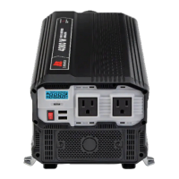
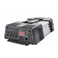
The primary function of the power inverter is to provide AC power from a DC source. It features two USB ports for charging USB-powered devices and AC outlets for connecting standard electrical appliances. The inverter is designed to automatically identify the battery's voltage (12 V or 24 V) upon initial connection and operate accordingly, setting appropriate low-voltage and high-voltage shutdown thresholds. For instance, if connected to a 24 V truck battery, it will operate with a low-voltage shutdown at 20–22 V and a high-voltage shutdown at 30–32.6 V. If the battery voltage is changed, the inverter needs to be powered off and reconnected to the new battery for proper voltage identification.
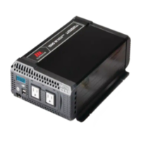
The device is equipped with several automatic safety features to ensure safe and trouble-free operation. These include a vehicle battery low-voltage automatic alarm and shutdown, which activates when the battery voltage drops to a critical level, turning the green indicator light red. The unit will automatically resume once the voltage is restored. Similarly, a high-voltage automatic shutdown is triggered if the battery voltage rises to a dangerously high level, also indicated by a red light, and will resume automatically.
Overload protection is another key safety feature. If a device rated more than 400 W is plugged into the inverter, it will automatically shut down, and the green indicator will turn red, requiring a manual restart. Overheat protection is activated if the inverter overheats due to improper ventilation or high ambient temperatures, leading to an automatic shutdown and a red indicator light, with automatic resumption once cooled. Output short-circuit protection and current leakage protection are also integrated, causing automatic shutdown and a red indicator light in case of a short-circuit or electric leakage in the connected device, requiring a manual restart. A built-in fan activates when a significant power increase raises the internal temperature beyond the ambient operating temperature, aiding in cooling. For continuous protection against fire or electric shock, the inverter includes a replaceable 8 A fuse.
Before connecting any devices, it is crucial to determine the maximum load the inverter can handle. Users should identify all devices they intend to power, add up their total wattage, and ensure this sum does not exceed the inverter's continuous power rating of 400 W. The inverter can supply momentary surge power up to 800 W, but exceeding this can cause damage. Wattage information can typically be found on the device's rating plate or in its instruction manual. If wattage is not listed, it can be calculated using the formula: VOLTS x AMPERE = WATTS. It is important to distinguish between rated (running) wattage, which is the continuous power consumption, and surge (starting) wattage, which is the power consumed at start-up for a limited time (2-3 seconds). Some devices, particularly those with induction motors, may have a start-up surge 3 to 7 times their rated wattage.
When connecting the power inverter, users must ensure it is placed on a flat, stable surface in a dry, cool, well-ventilated, and clean location. It should not be exposed to water, rain, moisture, snow, or spray, and should be kept away from heating vents and direct sunlight. Operating temperatures should be between 0°C and 40°C (32°F and 104°F), with optimal performance below 25°C (77°F). At least 2 inches (5 cm) of clearance should be allowed around the inverter for proper cooling. The inverter should not be installed in compartments with batteries or flammable liquids/vapors.
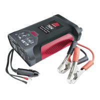
Connecting the inverter involves screwing off the caps of the DC cabling terminals, connecting the provided cables (red to positive, black to negative), and screwing the caps back on tightly. For loads under 100 W, the inverter can be connected to a vehicle's 12 V outlet using the DC cable with a 12 V outlet plug. For loads up to 400 W or when connecting to a 24 V vehicle battery, the DC cable with battery clamps should be used, connecting directly to the battery terminals. When connecting to a battery, a spark may be visible, so it's crucial to ensure the area is free of flammable fumes and well-ventilated. Jewellery should be removed to prevent short-circuits.
To switch on the inverter, the on/off switch (G) should be set to the "I" position. The power indicator light (F) will illuminate, signaling normal operation and that the AC outlet and USB port are powered. When plugging in multiple devices, they should be turned on one at a time to prevent surge current overload. The USB port provides 5 V/2.1 A DC power for external USB-powered devices, but does not support data communication.
Regular maintenance is essential for the longevity and safe operation of the power inverter. Before cleaning, the inverter must be switched off and disconnected from the power source. The exterior should be cleaned periodically with a damp cloth or sponge and a mild soap solution. It is crucial to ensure that the vents and fans are free of dust and debris to prevent overheating. The device should never be immersed in water or any other liquid, and corrosive detergents, wire brushes, abrasive scourers, or metal/sharp objects should not be used for cleaning.
The inverter should be stored in a cool, dry location, protected from moisture and out of reach of children. If the inverter is frequently used for extended periods, especially with the engine off, it is advisable to start the engine for 10-15 minutes at least once an hour to prevent battery discharge. Alternatively, consider connecting the inverter to a separate deep-discharge type of battery for prolonged use.
In case of a faulty fuse in the 12 V outlet plug of the connector cable, it must be replaced with a fuse of the same type and rating (125 V, 8 A) for continued protection against fire or electric shock. The replacement process involves screwing off the upper cover of the 12 V outlet plug, removing the faulty fuse, inserting a new one, and screwing the cover back on.
Troubleshooting guidance is provided for various issues, including low battery alarm/shutdown, high-voltage shutdown, overload shutdown, overheat shutdown, and situations where connected devices do not switch on or the inverter runs small loads but not larger ones. Solutions range from recharging or replacing the battery, disconnecting devices, clearing ventilation holes, moving the inverter to a cooler place, reducing the load, verifying charging system regulation, to checking connections and using only provided cables. For issues like television interference, adjusting the inverter's orientation, using a better antenna, or trying a different TV model are suggested. If the power inverter is damaged, it should be repaired by an authorized service center.
| Input Voltage | 12V DC |
|---|---|
| Output Voltage | 120V AC |
| USB Port | Yes |
| Frequency | 60Hz |
| Efficiency | 90% |
| Waveform | Modified Sine Wave |
| USB Ports | 1 |
| Cooling | Fan |
| Protections | Overload, Short Circuit, Over Temperature |