CONNECTIONS
1. Mount the MotorSaver
®
in a convenient location in or near the motor control panel. If the location is wet
or dusty, the MotorSaver
®
should be mounted in a NEMA 4 or 12 enclosure.
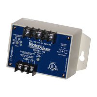
2. Connect the three lines of the motor’s 3-phase power supply to L1, L2 and L3 on the MotorSaver’s
terminal strip [Pin 3, 4 and 5 on the Model 201] (see Figure 1).
3. Connect the output relay to the circuitry to be controlled (see Figure 1).
SETTINGS
All models are not equipped with the same adjustments. Set the adjustments available on the front of your
particular model.
1. LINE VOLTAGE ADJUSTMENT: Rotate the LINE VOLTAGE ADJUSTMENT to the nominal 3-phase
line voltage feeding the motor to be protected.
2. TIME DELAY RESTART: Rotate the RESTART DELAY to the desired position. The restart delay is the time
between MotorSaver
®
seeing acceptable power and MotorSaver
®
closing its output contacts.
For compressor applications, the restart delay should be set for the approximate time it takes for the head
pressure to bleed off of the compressor. For other applications, the restart delay is typically set at 2 seconds.
If the RESTART DELAY is in the MAN (manual) position, the unit will not automatically restart until it is
turned out of the manual position.
3. TRIP DELAY ADJUSTMENT: Rotate the TRIP DELAY ADJUSTMENT to the desired setting.
The adjustment does not affect the trip delay on phasing faults. Typically, the TRIP DELAY ADJUSTMENT
is set to 4 seconds. In areas where voltage fluctuations are frequent, the TRIP DELAY ADJUSTMENT is
set between 10 and 15 seconds.
4. OTHER OPTIONAL ADJUSTMENTS: If your MotorSaver
®
is equipped with another optional adjustment,
rotate the adjustment screw to the desired setting.
POWER-UP
Turn on the power to the motor. The MotorSaver
®
then goes through its restart delay and the LED will flash
green. After the RESTART DELAY (fixed or adjustable), the MotorSaver
®
will energize its output contacts
and the RUN LIGHT will turn solid green. If the contacts do not energize and the RUN LIGHT does not turn
solid green, see the TROUBLESHOOTING section.
TROUBLESHOOTING
If the output relay does not energize and the RUN LIGHT does not turn solid green after waiting for the
RESTART DELAY time:
1. Rotate the RESTART DELAY dial clockwise 1/8 turn, above "2." You may be pointed at "Manual" or close
enough to the Manual reset position that the unit will not automatically restart. If the light does not flash
green, proceed to step 2.
(A) To control a motor: Connect the normally open contact in
series with the magnetic coil of the motor starter as shown.
(B) To sound an alarm: Connect the normally closed
contact in series with the alarm as shown.
Figure 1:Typical Wiring Diagram
 Loading...