EN
24
COM
PAR
OPEN
CLOSE
SBS
NEG
PH-POW
PH1
PH2
COM
FLASH
LED
SEN
COM
STOP
EDGE
EDGE
COM
ELEC
COM
IND
POWER
SUPPLY
N
T2A
L
230Vac
PHOTOTEST
LIGHT
TWILIGHT SENSOR
LED OUTPUT
STOP
OPEN
PHOTOCELL 1
PHOTOCELL 2
CLOSE
PARCIAL
STEP BY STEP
+ COMMON
+ COMMON
SAFETY EDGE
ELECTRIC LOCK
NEGATIVE
SBS
M1
M2
BATTERIES
(ACCESSORY)
COMMON
FLASH
SHIELD
ANT
PH1
RX
2
1
PH1
TX
SHIELD
ANT
COMMON
FLASH
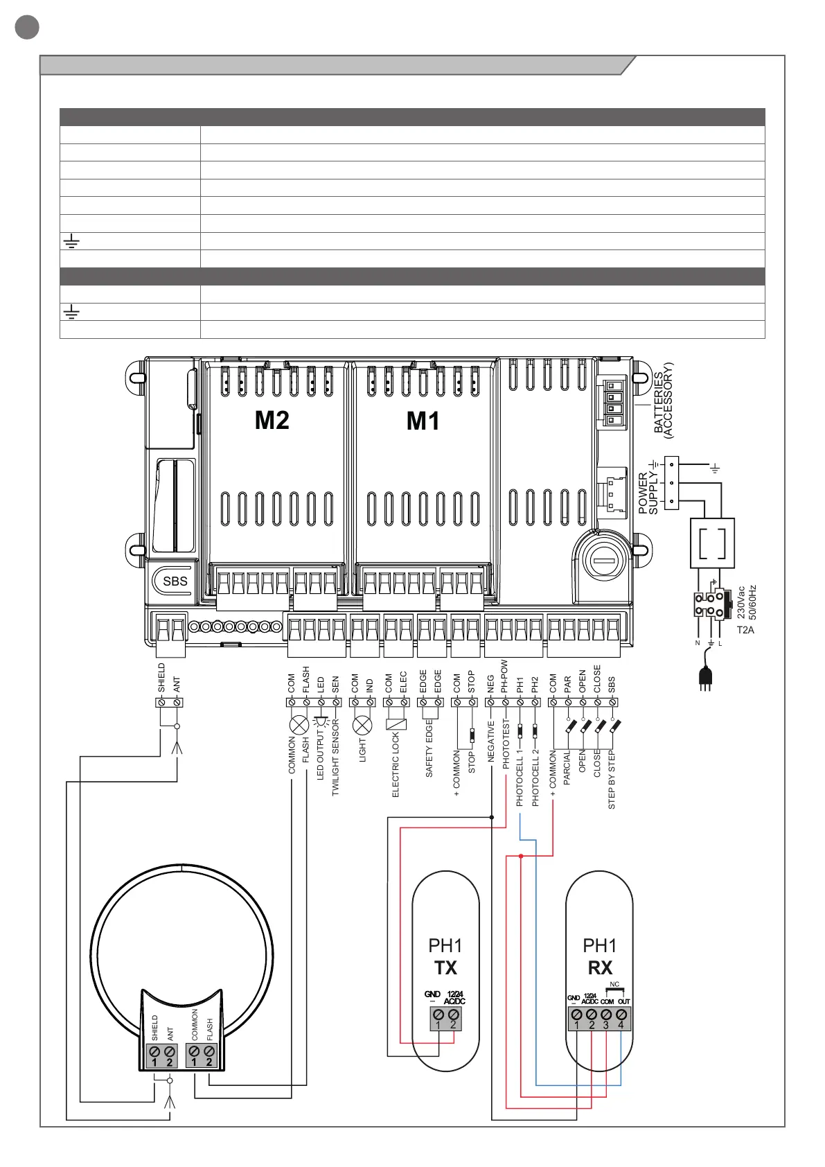
4.7 - Electrical connections
TRANSFORMER
WARNING - Before making the connections, ensure that the control unit is not powered up.
POWER MODULE CONNECTIONS
LS1 Limit switch 1 input (only for SLIDER)
LS2 Limit switch 2 input (only for SLIDER)
V+ Limit switch/encoder power supply positive common (12 Vdc 50 mA MAX)
ENC Encoder S signal input
NEG Encoder power supply negative
M- Motor output
Earth
M+ Motor output
POWER SUPPLY CONNECTIONS
L Power supply 230 Vac 50-60 Hz
Earth
N Power supply neutral 230 Vac 50-60 Hz