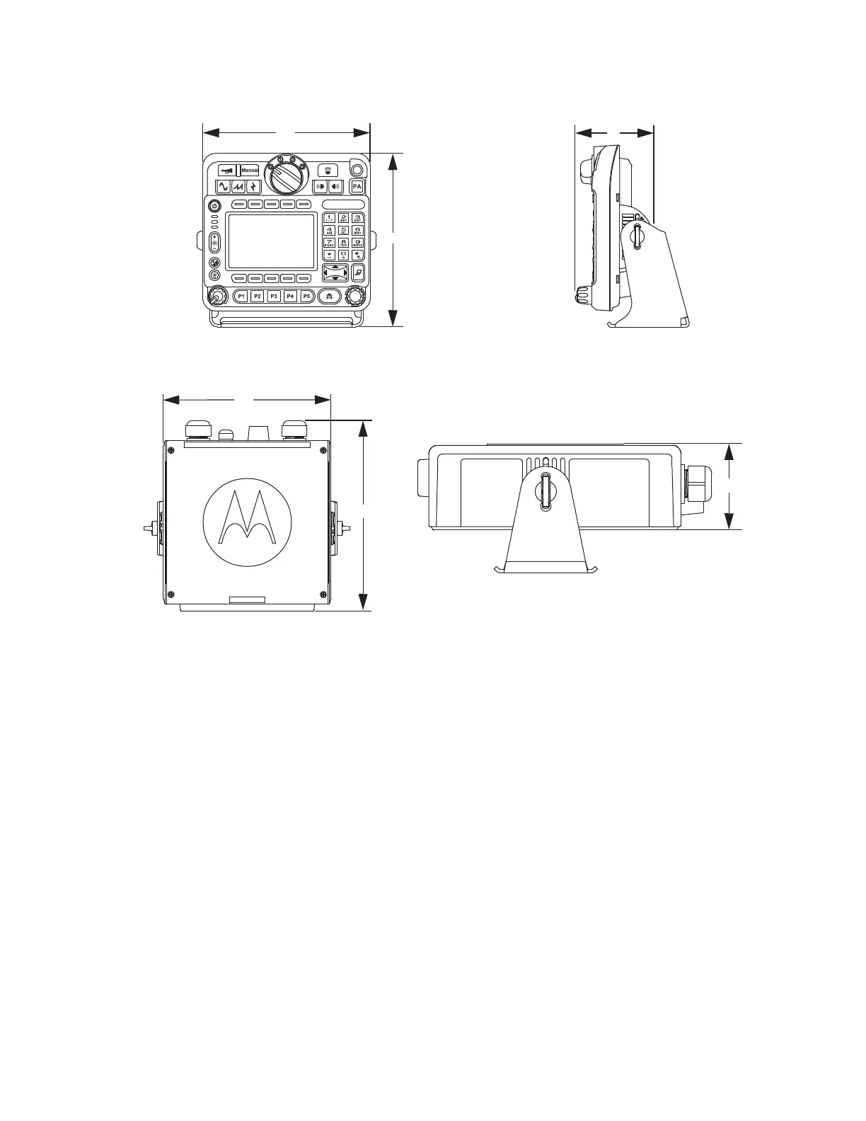
Figure 10: Front and Side View of O9 Control Head with Trunnion
Figure 11: Top and Side View of O9 Universal Relay Controller (URC) with Trunnion (URC is an
orderable accessory)
1.2
Standard Configurations
This chapter covers the dash mount, remote mount, and multi-control head configurations.
1.2.1
Dash Mount Configuration
There are two versions of the mobile dash mount.
The first are the O2, O5, E5, and O7 control heads which are mounted on the front of the transceiver
housing. The second is the O3 control head which is connected to the transceiver through a coiled
cable, which is plugged into the CAN connector on the transceiver.
Electrical connection between the two takes place within the radio through a flexible circuit board
between the connectors on the front of the transceiver and at the back of the control head for O2, O5,
E5, and O7 and between the connectors on the front of the transceiver and at the back of the TIB for
the O3.
MN005720A01-AB
Chapter 1: Introduction
23
 Loading...


