Home
Motorola
Two-Way Radio
CDM Series
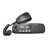
Motorola CDM Series Service Manual
178 pages
Manual
Specs
Ask a question
To Next Page
To Next Page
Loading...
CDM Series
™
PRO Series
™
Professional Series
T
wo-W
ay Mobile Radios
Detailed Service Manual
2
Table of Contents
Chapter 1: Service Maintainability
5
Table of Contents
5
About this Manual
7
Scope
7
Organization
7
Conventions
7
Introduction
7
Warranty and Service Support
7
Warranty Period and Return Instructions
8
After Warranty Period
8
Piece Parts Availability
8
Replacement Parts Ordering
8
Technical Support
9
Radio Model Information
9
Maintenance
11
Introduction
11
Preventive Maintenance
11
Inspection
11
Cleaning
11
General Repair Procedures and Techniques
12
Parts Replacement and Substitution
12
Rigid Circuit Boards
12
Chip Components
13
Shields
13
Safe Handling of CMOS and LDMOS
12
Notes for All Schematics and Circuit Boards
14
Service Aids
19
Recommended Service Tools
19
Recommended Test Equipment
21
Chapter 2: Control Head Service Information
23
CDM1250 / PRO5100 Model (GCN6113_)
25
CDM750 / PRO3100 Model (GCN6112_)
25
Overview
25
CDM1550 Series / PRO7100 Model (GCN6114_)
26
Theory of Operation
27
Control Head (CDM750 / PRO3100)
27
Power Supplies
27
Power On/Off
27
Microprocessor Circuit
27
SBEP Serial Interface
28
Keypad Keys
28
Status LED and Back Light Circuit
29
Microphone Connector Signals
29
Speaker
29
Electrostatic Transient Protection
30
Introduction
27
Control Head (CDM1250 / PRO5100 / CDM1550 Series / PRO7100)
30
Power Supplies
30
Power On/Off
30
Microprocessor Circuit
30
SBEP Serial Interface
31
Keypad Keys
31
Status LED and Back Light Circuit
32
Liquid Crystal Display (LCD)
32
Microphone Connector Signals
33
Speaker
33
Electrostatic Transient Protection
33
Passport Trunking Controller Board (PTCB)
34
Troubleshooting Charts
35
Control Head CDM750 / PRO3100 Troubleshooting Flow Charts
35
Troubleshooting Flow Chart for On/Off
35
Troubleshooting Flow Chart for Microprocessor
36
Control Head CDM1250 / PRO5100 / CDM1550 Series / PRO7100 Troubleshooting Flow Charts
37
Troubleshooting Flow Chart for On/Off
37
Troubleshooting Flow Chart for Microprocessor
38
Troubleshooting Flow Chart for Display
39
Troubleshooting Flow Chart for Back Light
40
Allocation of Schematics and Circuit Boards
42
Control Head CDM750 / PRO3100 PCB 8486146B07, Schematics, and Parts Lists
43
Control Head CDM1250 / PRO5100 / CDM1550 Series / PRO7100 PCB 8486155B06, Schematics, and Parts Lists
47
Chapter 3: Controller Service Maintainability
53
Controller Circuits
55
Overview
55
General
55
Radio Power Distribution
56
Electronic ON/OFF
58
Emergency
58
Mechanical ON/OFF
59
Ignition
59
Microprocessor Clock Synthesizer
59
Serial Peripheral Interface (SPI)
60
SBEP Serial Interface
61
General Purpose Input/Output
61
Normal Microprocessor Operation
62
FLASH Electronically Erasable Programmable Memory (FLASH EEPROM)
63
Electrically Erasable Programmable Memory (EEPROM)
63
Static Random Access Memory (SRAM)
64
Theory of Operation
55
Controller Board Audio and Signaling Circuits
64
Audio Signaling Filter IC with Compander (ASFIC CMP)
64
Transmit Audio Circuits
65
Transmit Signaling Circuits
67
Receive Audio Circuits
69
Receive Signaling Circuits
72
Voice Storage (Optional)
73
Troubleshooting Charts
75
Troubleshooting Flow Chart for Controller
75
Controller Schematics and Parts Lists
77
Allocation of Schematics and Circuit Boards
77
Controller Circuits
77
Voice Storage Facility
77
Controller T2 Schematics and Parts Lists
79
Controller T5 Schematics and Parts Lists
86
Controller T6/T7/T9 Schematics and Parts Lists
94
Chapter 4: Vhf (136-174 Mhz) 1-25W Service Information
121
Model Charts and Technical Specifications
123
VHF (136-174 Mhz) 1-25W Model Charts
123
CDM Series Model Chart
123
PRO Series Model Chart
124
Technical Specifications
124
Theory of Operation
127
Introduction
127
VHF (136-174 Mhz) 1-25W Receiver Front-End
127
Receiver Front-End
127
Front-End Bandpass Filters and Pre-Amplifier
128
First Mixer and High Intermediate Frequency
128
Low Intermediate Frequency (IF) and Receiver Back-End
128
VHF (136-174 Mhz) 1-25W Transmitter Power Amplifier (PA) 25W
129
First Power Controlled Stage
129
Power Controlled Driver Stage
130
Final Stage
130
Directional Coupler
130
Antenna Switch
131
Harmonic Filter
131
Power Control
131
VHF (136-174 Mhz) 1-25W Frequency Synthesis
131
Reference Oscillator
132
Fractional-N Synthesizer
132
Voltage Controlled Oscillator (VCO)
133
Synthesizer Operation
134
Troubleshooting Charts
135
Troubleshooting Flow Chart for Receiver
135
Troubleshooting Flow Chart for 25W Transmitter
137
Troubleshooting Flow Chart for Synthesizer
140
Troubleshooting Flow Chart for VCO
141
Allocation of Schematics and Circuit Boards
143
Controller Circuits
143
VHF (136-174 Mhz) 1-25W Pcbs, Schematics, and
143
VHF (136-174 Mhz) 1-25W PCB 8486172B04, Schematics, and Parts Lists
145
VHF (136-174 Mhz) 1-25W PCB 8486172B06, Schematics, and Parts Lists
155
VHF (136-174 Mhz) 1-25W PCB 8486172B07, Schematics, and Parts Lists
165
VHF (136-174 Mhz) 1-25W PCB 8486172B08, Schematics, and Parts Lists
172
Other manuals for Motorola CDM Series
Detailed Service Manual
686 pages
Basic Service Manual
92 pages
Service & Installation Manual
32 pages
Need help?
Do you have a question about the Motorola CDM Series and is the answer not in the manual?
Ask a question
Motorola CDM Series Specifications
General
Frequency Range (VHF)
136-174 MHz
Number of Channels
16
Frequency
VHF
Frequency Range (UHF)
403-470 MHz
Battery Life
8 hours (typical)
Related product manuals
Motorola CDM750
686 pages
Motorola CDM1250
686 pages
Motorola CDM1550 LS
5 pages
Motorola CDM1550-LS+
114 pages
Motorola CP100
62 pages
Motorola CP185
120 pages
Motorola CP200
88 pages
Motorola CP150
252 pages
Motorola clp446
46 pages
Motorola CLS1410
72 pages
Motorola CLS1110
66 pages
Motorola CLP446e
792 pages