Chapter 3: 2-1
6881091C63-A
Section 2
TROUBLESHOOTING CHARTS
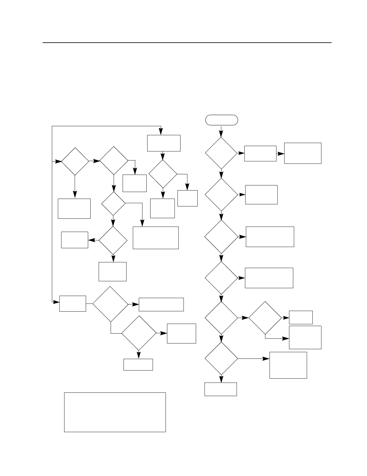
1.0 Troubleshooting Flow Chart for Controller
Power Up
Alert Tone
OK?
Speaker &
Control
head OK?
U0101
EXTAL=
7.3728 MHz/
14.7456
MHz?
BUS+
activity when
volume knob
rotated?
MCU is OK
Not able to
program
RF Board ICs
Before replacing
MCU, check SPI
clock, SPI data,
and RF IC select
Replace
Speaker /
Control Head
U0221 Pin 34 =
16.8 MHz?
Check
FGU
Reprogram the
correct data. &
Check ASFIC
and MCU
Check Control
head and MCU
(U0101, U0121,
U0122, U0111)
Press PTT. No
RF Output
Power.
Red LED
lights up?
Check
Control
head
Check
FGU &
Transmitter
Audio
at Pin 41
U0221?
Enable External PTT
with CPS
External PTT
enabled with
CPS?
Radio could
not PTT
externally
DC
at assigned
Acc. Con.
Pin DC
changes?
Check Components
between U0221 and
U0271
Check
Connection
to µP port
PTT
NO
YES
NO
YES
YES
YES
YES
NO
NO
YES
NO
YES
NO
YES
NO
YES
EXT
PTT
RX
AUDIO
Check
Accessories
J0501
Audio at Pin
16 &
Pin 1
Check Spk. Flex
Connection &
Control head
Audio
at Audio PA
(U0271)
input
Check
ASFIC
U0221
Check
Audio PA
(U0271)
Check
Receiver &
IF IC
Audio at
Pin 2
U0221?
NO
NO
NO
YES
YES
NO
YES
NO
Before troubleshooting the controller section
according to this chart please check the follow-
ing:
1. Check tuning and CPS settings
2. Check if Alert Tones are enabled
3. Check if Control Head is OK
4. Check board visually
9.3V
DC at Pin 5
of U0641?
YES
NO
5V DC at
Pin OUT of
U0651?
YES
NO
Check U0641, Q0641,
Q0661, D0660 &
D0661
Check U0651, D0651,
D0621
Controller
Check

 Loading...


