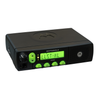
Controlhead Model for CM140 and CM340 2-3
If the BOOT_RES (J802-7) line is connected to >5V (e.g. 9.3V) at turn-on, the uP will start in boot
mode instead of normal operation. This mode is used to programme new firmware into the FLASH
memory (U404 mainboard).
2.6 Speaker
The controlhead contains a speaker for the receiver audio. The receiver audio signal from the
differential audio output of the audio amplifier located on the radio’s controller is fed via connector
J803-1, 2 to the speaker connector P801 pin 1 and pin 2. The speaker is connected to the speaker
connector P801. The controlhead speaker can be disconnected if an external speaker, connected on
the accessory connector, is used.
2.7 Electrostatic Transient Protection
Electrostatic transient protection is provided for the sensitive components in the controlhead by
diodes VR801, VR802, VR803 and VR804. The diodes limit any transient voltages to tolerable
levels. The associated capacitors provide Radio Frequency Interference (RFI) protection.

 Loading...