Controller Circuits 1-11
3.4 Keypad
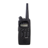
The keypad block diagram is shown at Figure 1-2. Pressing a key creates two distinct voltages,
KEYPAD_ROW and KEYPAD_COL. These voltages are routed to the microprocessor on the main
board. The microprocessor samples the voltages to determine which key has been pressed.
Figure 1-2 Keypad Block Diagram
3.5 Speaker and Microphone Assemblies
The speaker and microphone are mounted in the radio front housing. They are connected to the
audio circuits on the main board, the speaker via connector J491 pins 1 & 2 and the microphone via
connector J470 pins 1 & 2. Refer to the Audio Circuitry schematic diagram for details.
3.6 LCD Display Module
The display module is part of the keypad and is connected to the keypad board via a flex cable to
connector J1 on the keypad board.
Keypad
Button
MCP
Keypad Row
Keypad Row
Keypad Row
Keypad Column
Keypad Column
Keypad Column
28 Pin Connector
(keypad Board)
28 Pin Connector
(Main Board)

 Loading...