Allocation of Schematics and Circuit Boards 4-3
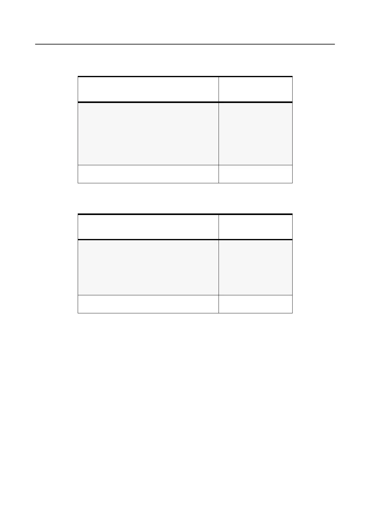
Table 4-4 VHF GP1280 Diagrams and Parts Lists
PCB :
8486101B11 Main Board Top Side
8486101B11 Main Board Bottom Side
Page 4-55
Page 4-56
SCHEMATICS
Controls and Switches
Receiver Front End
Receiver Back End
Synthesizer
Voltage Controlled Oscillator
Transmitter
Voice Storage Circuits
Page 4-39
Page 4-40
Page 4-41
Page 4-42
Page 4-43
Page 4-44
Page 4-19
Parts List
8486101B11 Page 4-57
Table 4-5 VHF Diagrams and Parts Lists
PCB :
8486473Z04 Main Board Top Side
8486473Z04 Main Board Bottom Side
Page 4-61
Page 4-62
SCHEMATICS
Controls and Switches
Receiver Front End
Receiver Back End
Synthesizer
Voltage Controlled Oscillator
Transmitter
Page 4-63
Page 4-64
Page 4-65
Page 4-66
Page 4-67
Page 4-68
Parts List
8486473Z04 Page 4-69

 Loading...


