Radio Disassembly — Detailed 3-9
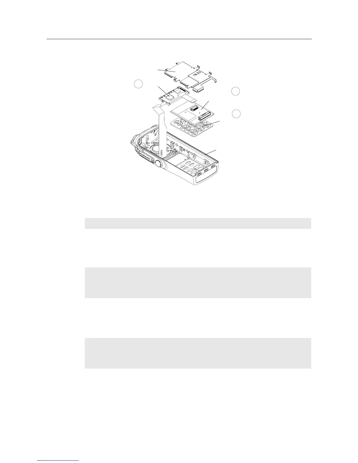
7. The keypad/option board, and the keypad, can be removed without the use of tools.
6.4 Speaker, Microphone, and Universal Connector Flex Disassembly
1. Turn the screw at the bottom of the dustcover counterclockwise with your fingers. Lift the
dustcover out of its pocket.
2. Using a screwdriver, push down on the portion of the speaker retainer bracket pointing toward
the bottom of the radio. Then, remove the retainer by slightly pushing it toward the top of the
radio until you slide it past the front cover slot.
3. Pull the rubber microphone boot from its seated position. Unless you are replacing the micro-
phone, leave it in the boot.
4. Peel-off the universal connector flex circuit escutcheon (label).
5. Pry the flex circuit (adhesive held) backer board away from the front cover, and remove the
universal connector tail of the speaker-microphone assembly through its opening in the front
cover.
Figure 3-7 Removing the Keypad Retainer and Other Boards from the Radio Body
NOTE
At this point, the Option Board Installation Procedure should be performed, if necessary.
NOTE
The dustcover must be removed to remove the speaker-microphone assembly flex circuit.
The speaker is held in place with a two-legged retainer bracket. The bracket legs are
secured by the front cover slots. Be careful not to damage the speaker when removing the
retainer bracket.
NOTE
The speaker-microphone assembly flex circuit goes through the front cover wall to the out-
side wall. To replace this assembly, you must peel-off the universal connector escutcheon
label. The existing escutcheon cannot be reassembled; a new part must be used. (See item
number 10 [GP360/380] on the exploded view drawing.)
Keypad/Option Board
Retainer
Display Module
Keypad
Radio Body
1
2
3
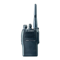
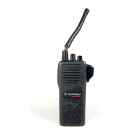
GP360/380
 Loading...