3-14 MAINTENANCE
8.0 Option Board Installation
1. With the keypad retainer removed, the keypad backer board can be removed without the use
of tools.
2. Remove the jumper flex from the connector on the keypad board. Notice the orientation of the
flex to the connector. Arrows on the jumper flex point to the correct way of inserting the flex
into the connector.
3. Discard the keypad backer board.
4. The “breakaway” tab at the top of all option boards contains an extra row of keys and is used
to accommodate other radio models.
5. Break-off and discard the option board tab, taking care not to damage the option board. Trim
any tab fragments that may remain on the option board.
6. Reassemble the option board to the front cover assembly.
7. Insert the display flex circuit into the connector on the option board.
8. Insert the jumper flex circuit into the connector on the option board. Notice the orientation of
the flex circuit. Arrows on the jumper flex point to the correct way of inserting the flex into the
connector.
9. Replace the retainer by placing the two top hooks into the slots below the speaker in the front
cover; then, pivot the retainer into the front cover. Ensure that all four tab arms snap correctly
into the front cover.
10. With the keypad option board, display, and retainer correctly in place, the front cover assem-
bly can now be reassembled as described in Paragraph 7.6 (Chassis and Front Cover Reas-
sembly).
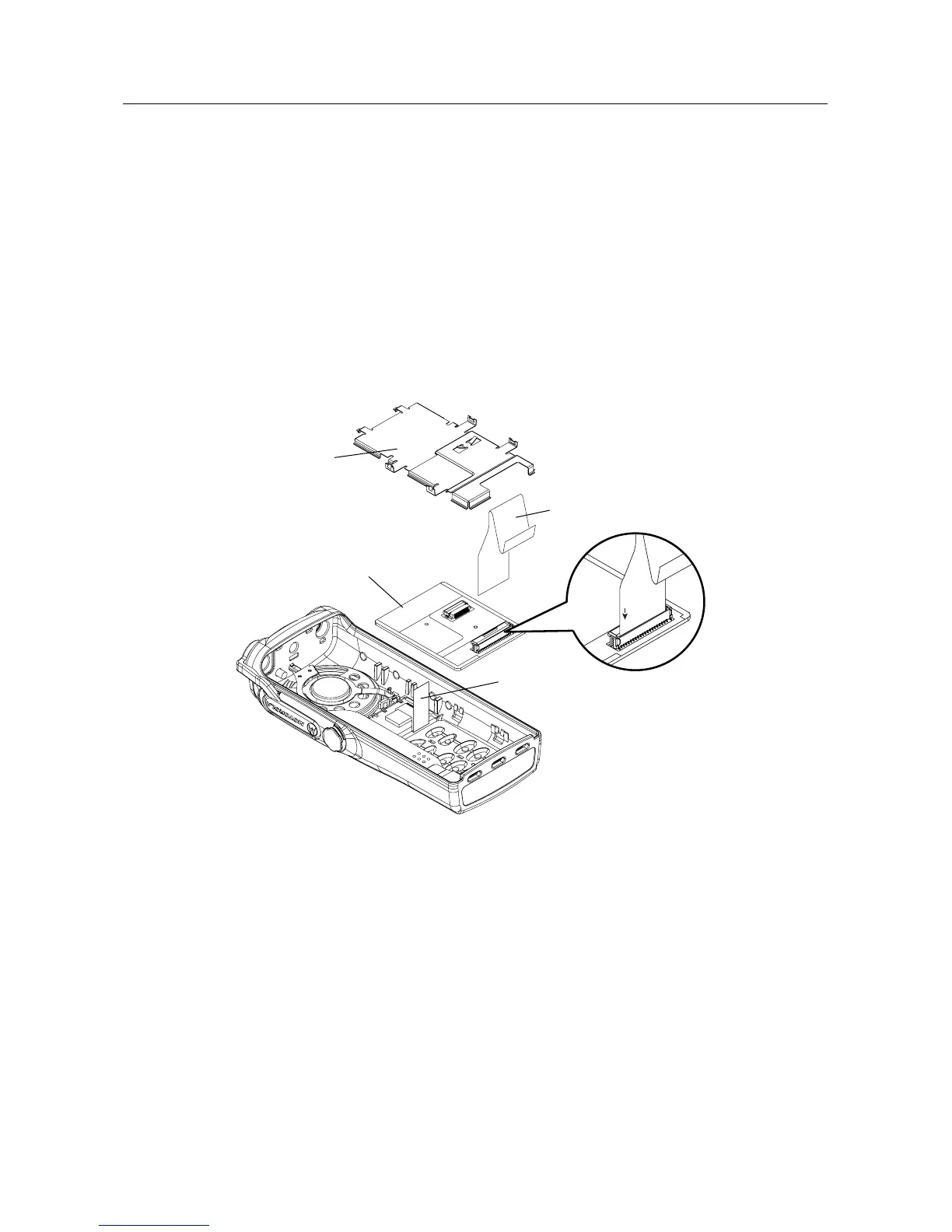
Figure 3-12 Changing the Keypad/Option Board
Retainer
Keypad/Option
Board
Display Flex
Jumper Flex
TO KP
 Loading...