3-6 MAINTENANCE
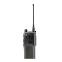
7. Lift the latches on the main circuit board to release the flexes from their connectors.
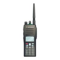
6.2 Chassis Assembly Disassembly
1. Use a TORX™ screwdriver with a T6 head to remove the four screws holding the main board
to the chassis.
2. Lift the main board from the chassis (See Figure 3-5).
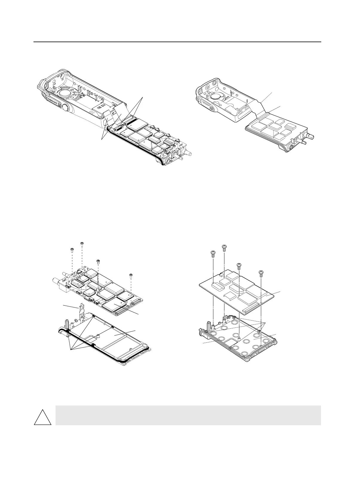
3. Remove the four small O-ring retainers from their slots in the chassis. Note the alignment of
the retainers for reassembly.
4. Remove the O-ring.
5. Slide off the ground contact from the top corner boss of the radio chassis.
Figure 3-4 Unlatch Flex Connectors
Figure 3-5 Remove Main Board from Chassis
CAUTION: Refer to the CMOS CAUTION paragraph on page 2 before removing the main
board. Be sure to use ESD protection when handling circuit boards.
Latches
Flex Connectors
Flex Connector
Latch
GP320/340/360/380
GP344/388
Main Board
Compliant
Ground
Contact
O-ring
Retaining
Features
Radio Chassis
Main Board
Radio Chassis
O-ring retaining
features
O-ring
GP320/340/360/380
GP344/388
!
 Loading...