INSTALLATION MTM800 Enhanced Mobile Terminal Installation Manual 67
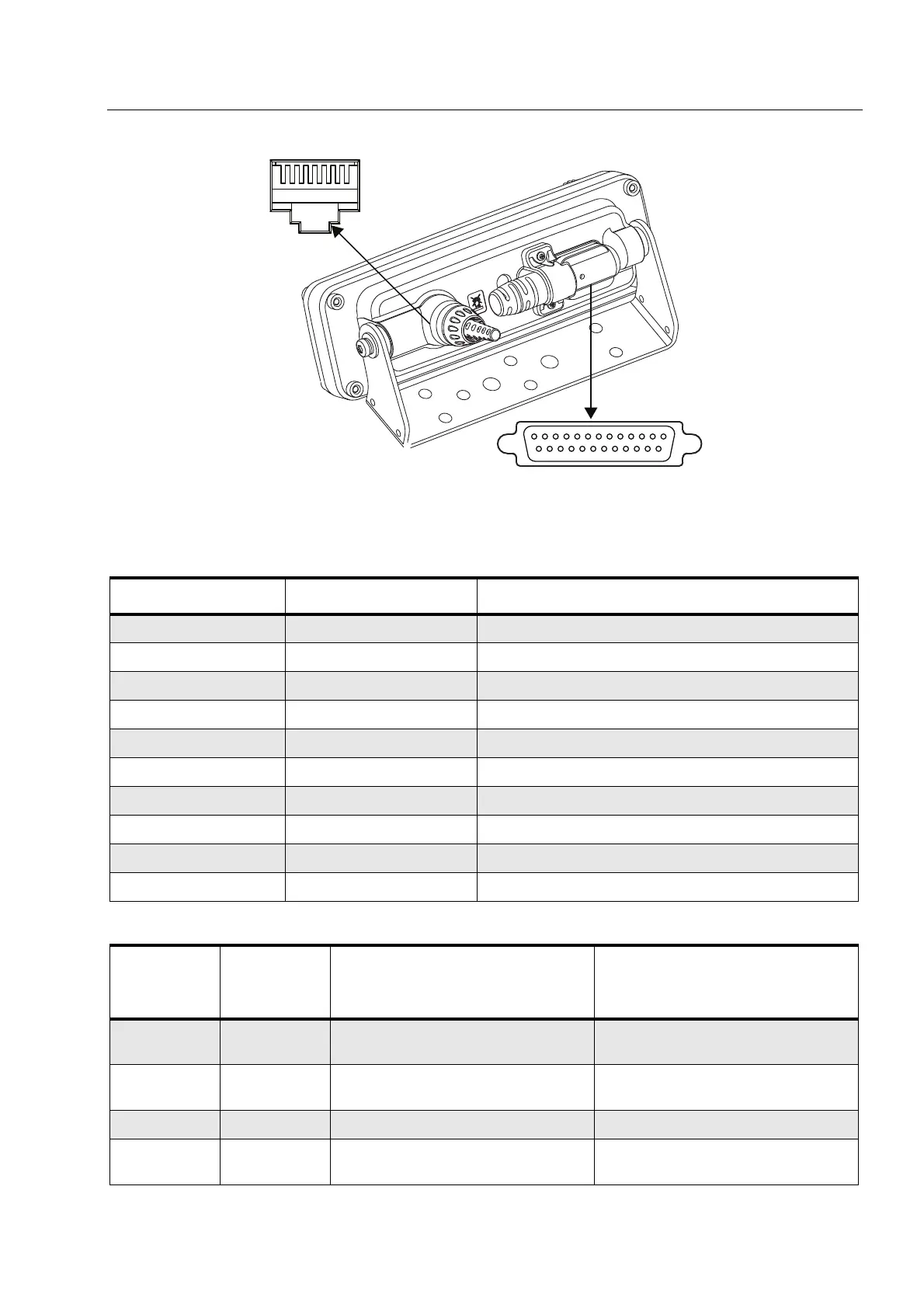
Figure 30 View of the Enhanced Control Head’s rear connectors
Table 15 10-Pin Telco Connector
Telco Connector Pin Function Description
1 AUDIO + Balanced Audio + (Bidirectional)
2 SPKR + Speaker +
3 BUS + Serial Bus, Data sent from the Enhanced Control Head
4 AUDIO - Balanced Audio - (Bidirectional)
5 SPKR - Speaker -
6 GND Ground
7 ON_OFF_CONTROL Radio Turn-On Signal
8 SCI_TX Serial Bus, Data sent to the Enhanced Control Head
9 FLT_A + Supply voltage
10 GND Ground
Table 16 25-Pin Back Connector
Back
Connector
Pin
Function Description Default
1 GPIO_9 GPIO Output: Active for duration of call (car
radio mute)
2 GPIO_6 GPIO PTT Input, TX audio from
MIC_REAR_2
3 GPIO_8 GPIO Disabled
4 GPIO_3 GCAI PIN 2 PTT Input, TX audio from
MIC_REAR_1
10-Pin Telco Connector
25-Pi n Back Connector
 Loading...