66 MTM800 Enhanced Mobile Terminal Installation Manual INSTALLATION
Connector and Pin Assignment of the Enhanced Control
Head
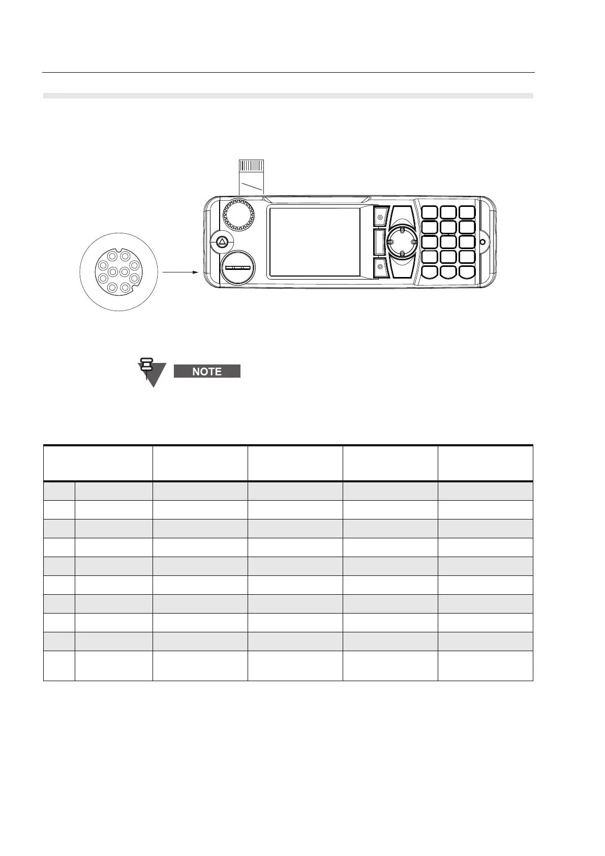
Figure 29 View of the Enhanced Control Head’s Mobile Microphone Port Connector and Flex Cable
The keypad labelling of the control head may vary
according to the specific customer/country concerns.
Table 14 10-Pin Mobile Microphone Port (MMP) Connector
Mobile Microphone
Port Pin
Default
Functions
Alternative
Functions
USB Functions RS232 Functions
1 1-WIRE 1-WIRE 1-WIRE 1-WIRE 1-WIRE
2 GPIO_3 PTT GP Input or Output GP Input or Output RS-232-RTS
3 SPEAKER SPEAKER SPEAKER SPEAKER SPEAKER
4 GPIO_2 GPIO_2 INPUT GP Input or Output DATA - RS-232-RXD
5 GND GND GND GND GND
6 OPT 5V HIGH Impedance OPT 5V VBUS OPT 5V
7 MIC + MIC + MIC + MIC + MIC +
8 GPIO_1 GPIO_1 INPUT GP Input or Output DATA + RS-232-TXD
9 GPIO_4 HOOK GP Input or Output GP Input or Output RS-232-CTS
10 GPIO_0 GPIO_0 INPUT GP Input or Output,
PWR ON
GP Input or Output,
PWR ON
GP Input or Output,
PWR ON
o
Pin 12
Flex
Cable
21
3
7
9
10
8
4
56
Front View of the Mobile
Microphone Port (MMP)
Connector
 Loading...