VHF Duplexer Module
68P81085E16-B 15
09/30/05
Boonton 92E RF
Millivoltmeter
Range set to +10dBm
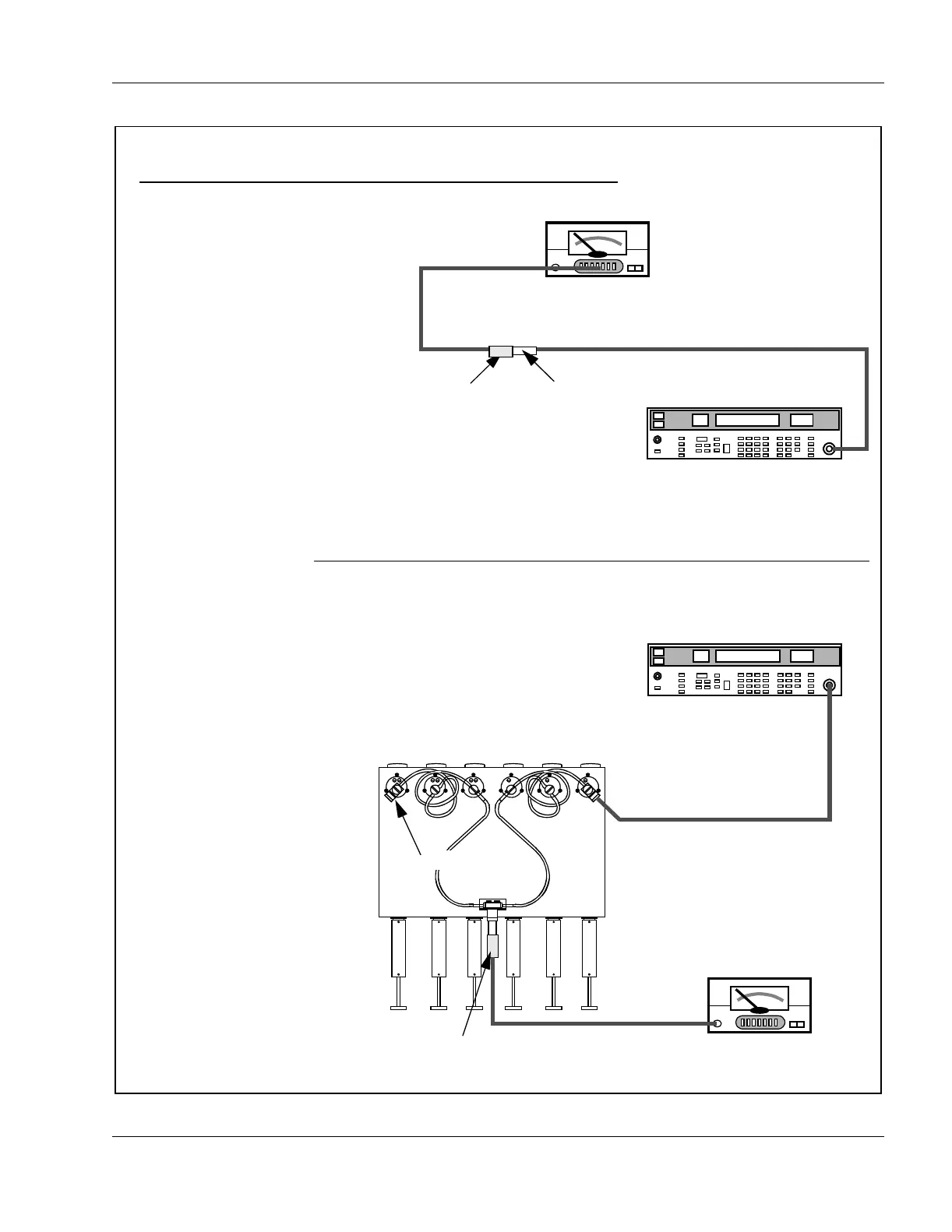
Figure 9. VHF Duplexer Field Tuning Procedure (Continued)
6. Verifying Insertion Loss
1. Connect test equipment as
shown.
2. Observe and note the level in
dBm as shown on the millivolt-
meter.
3. Connect the duplexer cable as-
sembly and test equipment to the
duplexer as shown.
4. Observe and note the level in
dBm as shown on the millivolt-
meter.
5. Subtract the absolute number
noted in Step 2 from the number
noted in Step 4. The difference
should be less than 1.3 dB to
meet specification for Insertion
Loss.
6. Repeat Steps 1 to 5 for Low-
Pass/High Notch cavities with the
following exceptions:
a) Set Frequency Generator for
Rx or Tx frequency,
whichever is LOWER
b) Connect Signal Generator to
Low Pass duplexer input
(cavity #1)
c) Connect terminator to cavity
#6.
Frequency set to Rx or Tx frequency,
whichever is HIGHER.
Output Level set to +10dBm.
Boonton 92E RF
Millivoltmeter
HP8656B Signal Generator
HP8656B Signal Generator
6dB In-line
pad (50Ω)
UG349A N-to-
BNC Connector
Terminator
6dB In-line
pad (50Ω)
1 2 3 4 5 6
 Loading...