9-6 VHF Troubleshooting Tables: Troubleshooting Table for Board and IC Signals (VHF)
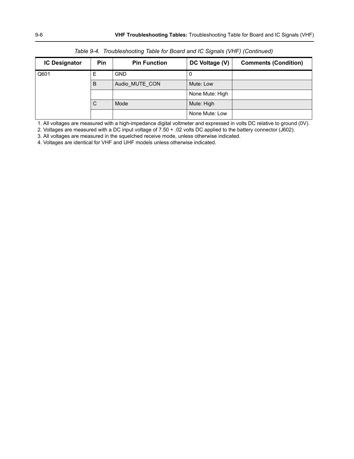
Q601 E GND 0
B Audio_MUTE_CON Mute: Low
None Mute: High
C Mode Mute: High
None Mute: Low
1. All voltages are measured with a high-impedance digital voltmeter and expressed in volts DC relative to ground (0V).
2. Voltages are measured with a DC input voltage of 7.50 + .02 volts DC applied to the battery connector (J602).
3. All voltages are measured in the squelched receive mode, unless otherwise indicated.
4. Voltages are identical for VHF and UHF models unless otherwise indicated.
Table 9-4. Troubleshooting Table for Board and IC Signals (VHF) (Continued)
IC Designator Pin Pin Function DC Voltage (V) Comments (Condition)

 Loading...


