435 – 480 MHz UHF2 Theory of Operation: UHF2 Transmitter 5-3
5.2.2 Receiver Back End
The 1st IF signal is amplified about 15 dB by IF amp Q303. The output of the IF amp is connected to
IF IC (U201). 1st IF frequency (45.1 MHz) and 2nd LO frequency (44.645 MHz) are mixed in U201.
The second mixer converts the 45.1 MHz high IF frequency to 2nd IF frequency (455 kHz).
Additional IF selectivity is provided by two ceramic filters (CF1, CF2). The wider filter 455 FW is used
for 20 kHz and 25 kHz channel spacing, and the narrower filter 455 HW is used for 12.5 kHz channel
spacing. These two ceramic filters may eliminate undesired signal and demodulated by demodulator
in U201. N/S_SW, which connected to microprocessor is used to select the wide and narrow band.
The mute (squelch) circuit switches off the audio amplifier when no audio is present. The squelch
circuit consists of U201 and U202 and their associated components. The noise signal from Pin 9 of
U201 is used to control the squelch circuit sensitivity of U202. The noise passes through filter, and is
amplified by internal amp of U201. The amplified noise act as a DC voltage to control the mute
system. So if the noise level is under the threshold voltage, the microprocessor (U101) un-mutes the
radio. If the noise level is over the threshold voltage, the microprocessor mutes the radio.
The squelch level is tuned in the factory. When a component or a part in the RX system is replaced,
the squelch must be re-tuned using the Tuner.
5.3 UHF2 Transmitter
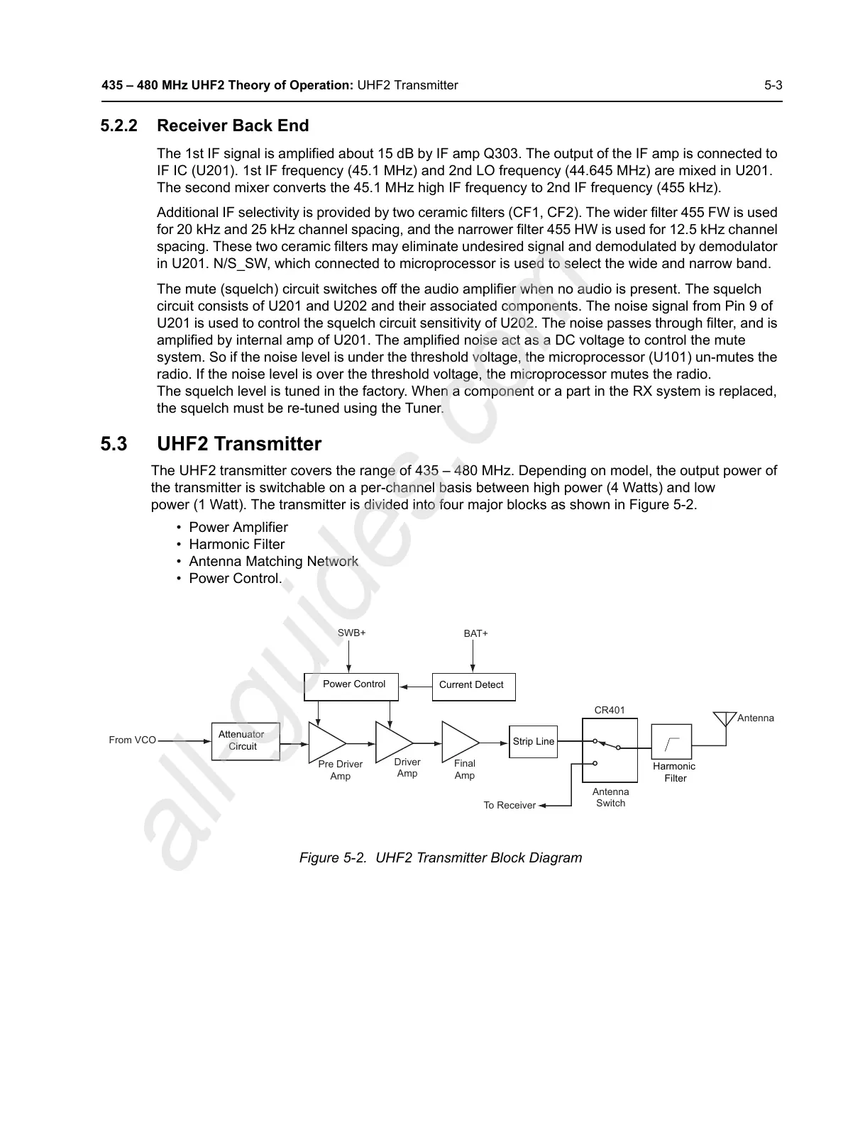
The UHF2 transmitter covers the range of 435 – 480 MHz. Depending on model, the output power of
the transmitter is switchable on a per-channel basis between high power (4 Watts) and low
power (1 Watt). The transmitter is divided into four major blocks as shown in Figure 5-2.
• Power Amplifier
• Harmonic Filter
• Antenna Matching Network
• Power Control.
Figure 5-2. UHF2 Transmitter Block Diagram
Attenuator
Circuit
Pre Driver
Amp
From VCO
Driver
Amp
Final
Amp
Power Control
Strip Line
Current Detect
SWB+
BAT+
Antenna
Switch
To Receiver
CR401
Harmonic
Filter
Antenna

 Loading...


