Controller Theory of Operation: TX Audio Circuit 4-3
4.2 TX Audio Circuit
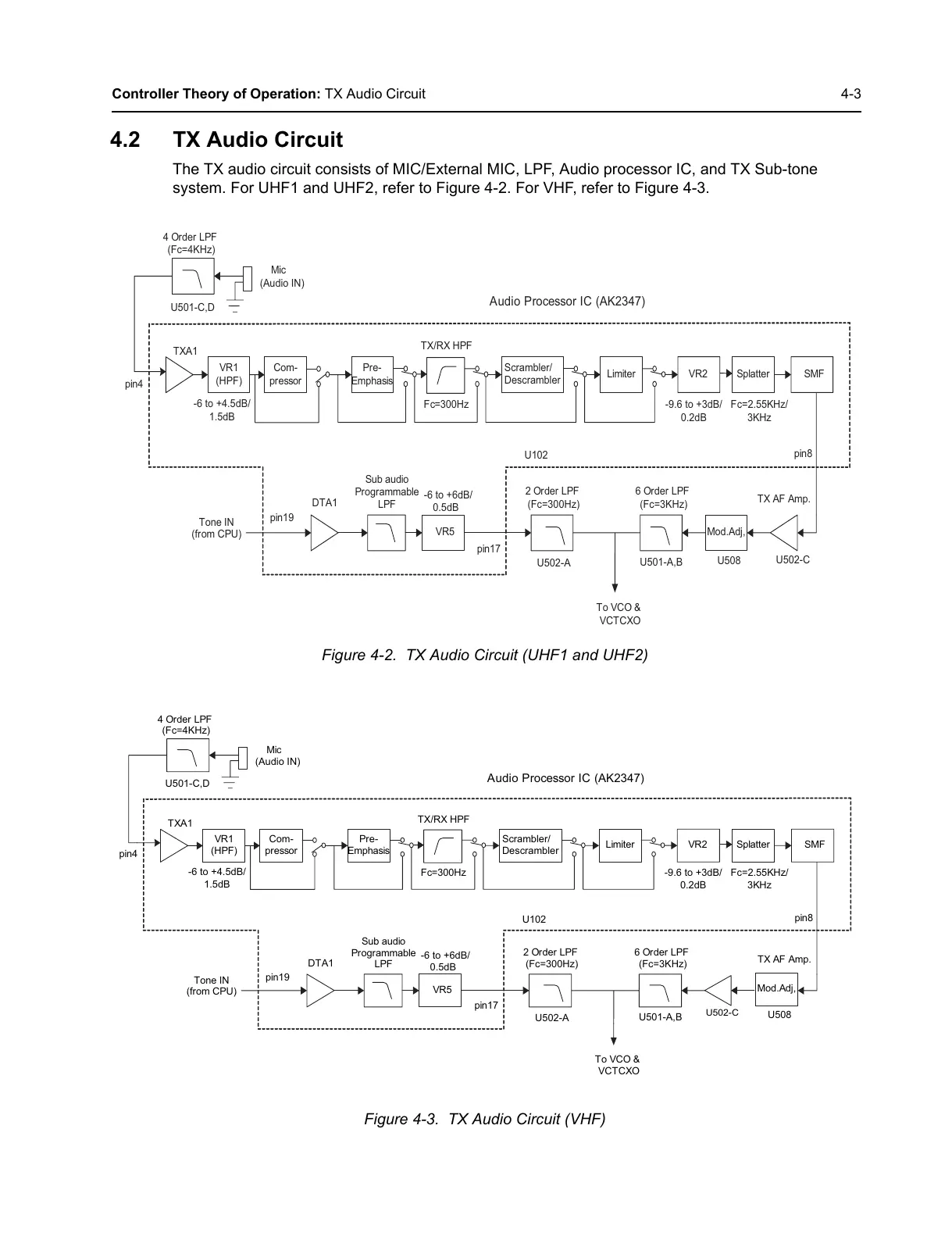
The TX audio circuit consists of MIC/External MIC, LPF, Audio processor IC, and TX Sub-tone
system. For UHF1 and UHF2, refer to Figure 4-2. For VHF, refer to Figure 4-3.
Figure 4-2. TX Audio Circuit (UHF1 and UHF2)
Figure 4-3. TX Audio Circuit (VHF)
VR1
(HPF)
Limiter
Scrambler/
Descrambler
Splatter SMF
TX/RX HPF
TXA1
-6 to +4.5dB/
1.5dB
-9.6 to +3dB/
0.2dB
Audio Processor IC (AK2347)
Tone IN
(from CPU)
VR5
Sub audio
Programmable
LPF
pin4
pin17
pin8
U102
-6 to +6dB/
0.5dB
Fc=300Hz
VR2
Pre-
Emphasis
Com-
pressor
DTA1
pin19
To VCO &
VCTCXO
2 Order LPF
(Fc=300Hz)
U502-A
Mod.Adj,
6 Order LPF
(Fc=3KHz)
U501-A,B
U508
T
X AF Amp.
U502-C
4 Order LPF
(Fc=4KHz)
U501-C,D
Mic
(Audio IN)
Fc=2.55KHz/
3KHz
VR1
(HPF)
Limiter
Scrambler/
Descrambler
Splatter SMF
TX/RX HPF
TXA1
-6 to +4.5dB/
1.5dB
-9.6 to +3dB/
0.2dB
Audio Processor IC (AK2347)
Tone IN
(from CPU)
VR5
Sub audio
Programmable
LPF
pin4
pin17
pin8
U102
-6 to +6dB/
0.5dB
Fc=300Hz
VR2
Pre-
Emphasis
Com-
pressor
DTA1
pin19
To VCO &
VCTCXO
2 Order LPF
(Fc=300Hz)
U502-A
6 Order LPF
(Fc=3KHz)
U501-A,B
Mod.Adj,
U508
TX AF Amp.
U502-C
4 Order LPF
(Fc=4KHz)
U501-C,D
Mic
(Audio IN)
Fc=2.55KHz/
3KHz

 Loading...


