3-2 TROUBLESHOOTING CHARTS
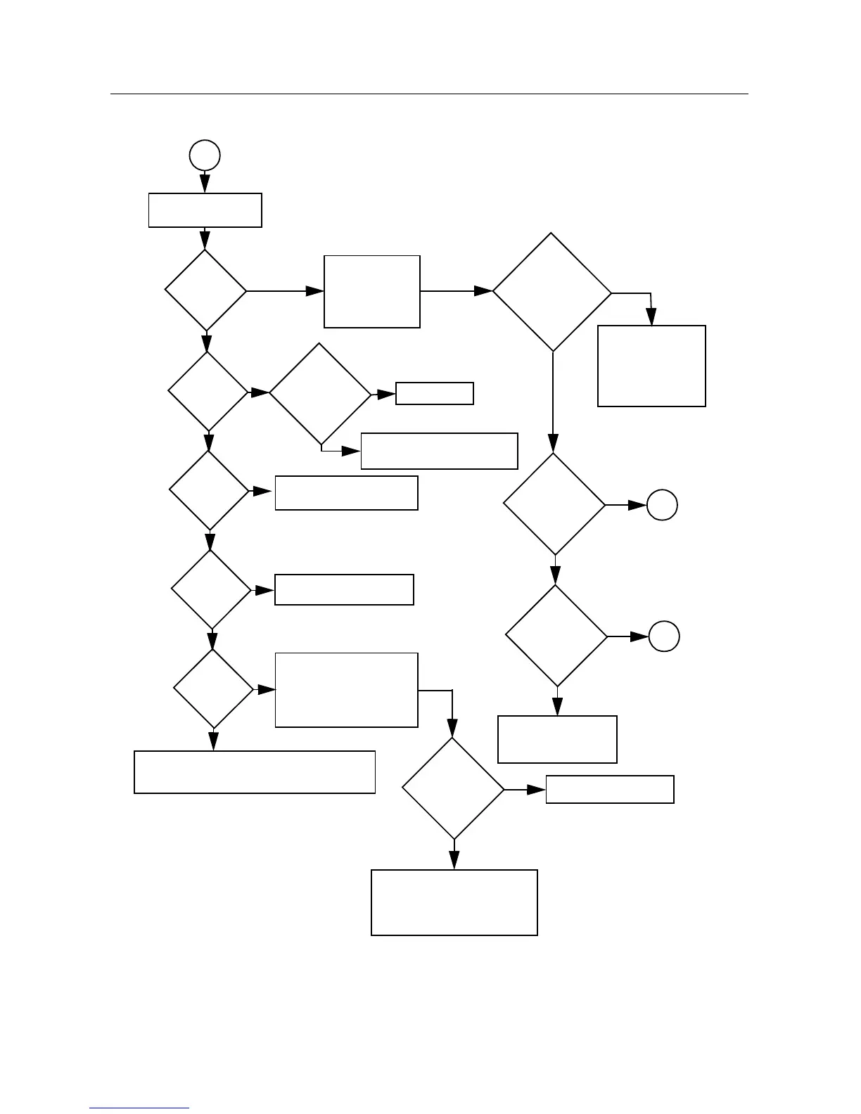
2.0 Troubleshooting Flow Chart for Receiver (Sheet 2 of 2)
Check filter between C301
& C307; program filter to
schematic test freq and
check varactor voltages.
Check Q210, U201
(pin 48) voltages
and U247
Check harmonic filters L101 & L102
and ant. switches CR101, CR102, L104
Is R5
present?
RF
Signal
at C310?
Trace IF signal
from L311 to
Q302. Check for
bad XTAL filter.
IF Signal
at L311?
No
RF
Signal
at T301?
No
RF
Signal
at C307?
No
RF
Signal
at C301?
No or
Inject RF into J101
Are varactor
voltages OK?
No
Yes
Check RF amp
(Q301) Stage.
Check filter between
C310 & T301.
Yes
Check T301, T302, CR306,
R308, R309, R310
Yes
1st LO O/P
OK?
Locked?
Yes
Check FGU
Yes
No
Yes
Q302
collector OK?
IF signal
present?
Yes
Check for 2.6
VDC
No
No
No
Check U404 voltage. U404
can be selected by MCU
before replacing U404.
Check varactor filter.
No
Yes
Yes
Yes
A
A
B
weak RF
Before replacing
U301, check
U301 voltages;
trace IF signal
path.
 Loading...


