Radio Exploded Mechanical Views and Parts Lists 2-15
8.0 Radio Exploded Mechanical Views and Parts Lists
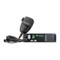
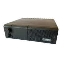
8.1 Radio Assembly - 1-25 W Models
Figure 2-14 Radio Assembly - 1-25 W Models
Table 2-1 Radio Assembly Parts List - 1-25 W Models
Item No. Description Part Number
1 Upper Cover 1589224U01
2 Main Seal 3289329U01
3 Bumper 7587509V06
4 Main Shield 2689338U01
5 PA Shield 2689337U01
6 Screw 0310943J12
7 PA Clip 0789352U01
8 VHF Main PCB
UHF Main PCB
See Chapter 7 Model
Charts and
Specifications.
9 Connector Jack:
Mini UHF
BNC
5802810C15
5802810C16
10 O-Ring 5802810C15
11 Power Cable Assembly 0189484U01
12 Cap, Accessory Connector 3202607Y01
13 Chassis 25W 2789223U01
14 Felt 3586661Z01
 Loading...