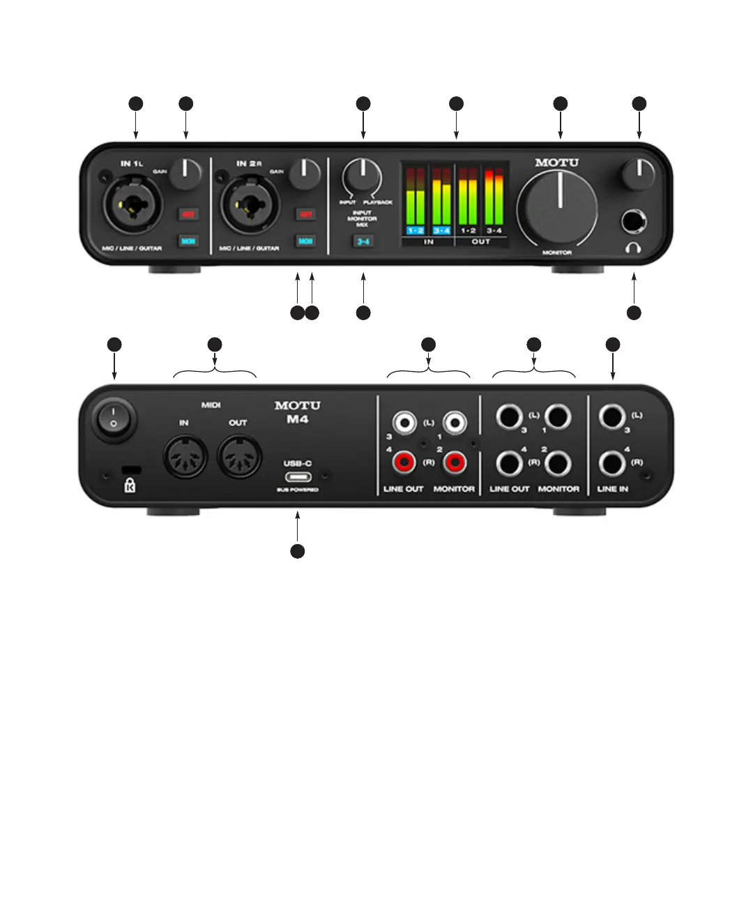
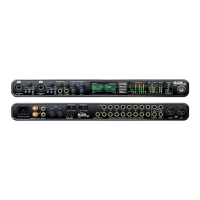
M4 Quick Reference
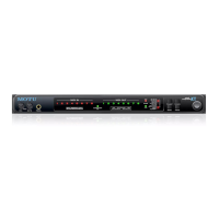
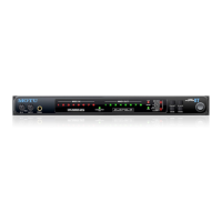
1. These two XLR/TRS combo jacks accept a mic cable or a
quarter-inch cable, balanced or unbalanced, from a guitar
or line level source.
2. Use GAIN knob to add up to 60 dB of boost to the input
signal. Watch the input level meter in the LCD while
adjusting gain. Try to adjust gain as high as possible
without clipping, which is indicated by the red rectangle at
the top of the meter.
3. INPUT MONITOR MIX: Controls the balance (relative
volume) between computer output (over USB) and live
inputs being monitored through the hardware using the
MON (monitor) button (10). Turn it counterclockwise to
hear more inputs; turn it clockwise to hear more computer
audio.
4. The full-color, high-resolution LCD (160x120 pixels) shows
full-length meters for all inputs and outputs. An
overloaded signal is indicated by a red box at the top of the
signal. If you see the red box, reduce the signal level. A blue
box around the input channel number indicates that
hardware (direct) monitoring (the MON button) is
engaged for that channel.
5. Volume control for the MONITOR outputs on the back
panel.
6. Volume control for headphone output.
7. Connect your headphones here. This signal matches the
signal on the MONITOR outputs on the rear panel, but
volume control (6) is independent.
8. Engages hardware (direct) monitoring for inputs 3-4 on
the rear panel. See (10) below for more information.
9. Engage the 48V button to engage phantom power for a
condenser microphone connected to the input.
10. Engage the MON (monitor) button to enable hardware
(direct) monitoring, which routes the channel’s input
signal directly to the outputs and pans the mono signal
evenly across both outputs (1-2). A blue box appears
around the input channel number in the LCD to indicate
that hardware monitoring is engage. Press and hold the
MON button to engage stereo monitoring for both inputs.
In this mode, Input 1 is routed to Output 1 and Input 2 is
routed to Output 2, allowing you to monitor in stereo while
recording in stereo.
11. POWER SWITCH: You can switch off the M4 and turn it back
on without restarting your computer.
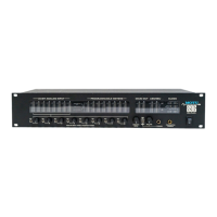
12. Connect MIDI gear to these standard MIDI ports.
13. These unbalanced RCA analog outputs mirror the signal on
their corresponding quarter-inch outputs (14). You can
connect them to a second set of speakers or other destina-
tions.
14. Connect these balanced, DC-coupled quarter-inch outputs
to your studio speakers, PA or other desired audio destina-
tion. They can also accept an unbalanced plug. Each output
pair is independent and can be found as separate output
pairs in your host software.
Note: the analog outputs are not cross-coupled. Therefore,
when connecting them to an unbalanced input, use a TRS
plug with the ring disconnected. Not floating the negative
terminal will short it to the sleeve ground and cause
distortion.
15. These LINE INPUTS accept either a balanced or unbalanced
plug. Connect a keyboard or other similar line level audio
source.
16. Connect the M4 to your host computer with the supplied
USB-C to USB-A cable. If your computer has USB-C ports,
use a USB-C to USB-C cable (rated for USB2) or a USB-A
adapter (both sold separately). The M4 is powered by its
USB connection to the host computer.
2
12
4 6
7910
11
1 5
15
16
3
8
13 14