- 10 -
DIP Switch Setting Description
– – Serves no function (reserved for future use).
BSP ON Enables broadcast storm protection
OFF Disables broadcast storm protection
ATTENTION
To actively update DIP switch settings, power off and then power
on the EDS.
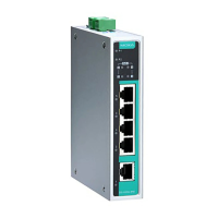
LED Indicators
The front panel of the EDS switches contain several LED indicators. The
function of each LED is described in the following table.
LED Color State Description
P1 AMBER On
Power is being supplied to power input
P1.
Power is not being supplied to power
Power is being supplied to power input
P2.
Power is not being supplied to power
AMBER On TP port’s 10/100 Mbps link is active.
Blinking
Data is being transmitted at 10/100
TP Port’s 10/100 Mbps link is inactive.
TP port’s 1000 Mbps link is active.
Data is being transmitted at 1000
TP Port’s 1000 Mbps link is inactive.
1000 GREEN On SFP module’s 1000Mbps link is active.
Data is being transmitted at 1000
Off SFP module’s 1000Mbps link is
inactive.
The PoE device is connected by IEEE
802.3af standard
Off No PoE power output or no PoE
The PoE device is connected by IEEE
802.3at standard
Off No PoE power output or no PoE
- 1 time/s: PoE standard detection
1x…………...failure
- 2 times/s: PoE current overload
Off No PoE failure
 Loading...