Do you have a question about the Moxa Technologies EDS-510E Series and is the answer not in the manual?
Lists items included in the EDS-510E package for verification upon receipt.
Highlights capabilities like redundant ring, security protocols, and industrial protocols.
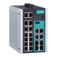
Details the front panel layout, including ports, status LEDs, and model name.
Describes the top panel components such as the reset button, DIP switches, and terminal blocks.
Outlines the rear panel features for mounting the device, including screw holes and DIN-rail kit.
Provides detailed measurements for the device's front, side, and rear views in millimeters and inches.
Shows dimensions for the DIN-rail and wall mounting kit components.
Step-by-step instructions for mounting the EDS-510E onto a DIN rail.
Guides on how to safely remove the EDS-510E from a DIN rail using a screwdriver.
Instructions for attaching wall mount plates and securing the device to a wall.
Critical warning about disconnecting power and adhering to voltage safety standards for wiring.
Notes on fire enclosure regulations for built-in unit installations.
Emphasizes disconnecting power, calculating current, and following electrical codes for safe wiring.
Explains grounding for EMI and how to wire the relay output contact.
Step-by-step guide for connecting redundant DC power inputs to the terminal blocks.
Instructions for connecting digital input signals to the 4-pin terminal block.
Lists the types and number of communication ports available on the EDS-510E switch.
Explains how to connect via the USB console port for configuration using terminal software.
Details the USB storage port usage for backups, firmware upgrades, and log file transfers.
Provides pinout configurations for both MDI and MDI-X RJ45 Ethernet ports.
Illustrates wiring for straight-through and cross-over Ethernet cables for RJ45 connections.
Details the specific MDI/MDI-X port pinouts for 1000BaseT connections over copper wires.
Describes SFP fiber ports, LC port pinouts, and cable wiring for optical connections.
Explains how to use the reset button for factory defaults and ABC-02-USB backup operations.
Details DIP switch settings for configuring the Turbo Ring Master and Coupler functions.
Explains DIP switch settings for the advanced Turbo Ring V2 protocol.
Describes the function of STATE, FAULT, PWR1, PWR2, and MSTR/HEAD LEDs.
Details the CPLR/TAIL, 10M/100M, and 1000M LEDs for ring status and port activity.
Lists standards, protocols, interfaces, power, and connection specifications.
Covers housing, dimensions, installation methods, and environmental operating limits.
Lists safety, EMI, EMS, shock, free fall, and vibration compliance standards.
Provides contact phone numbers and fax for Moxa technical support in various regions.
| Brand | Moxa Technologies |
|---|---|
| Model | EDS-510E Series |
| Category | Switch |
| Language | English |