NPort IA5150A/5250A
Quick Installation Guide
First Edition, December 2010
1. Overview
The NPort IA5150A/IA5250A series device servers deliver easy
and reliable serial-to-Ethernet connectivity for the industrial
automation market. The servers support several operation
modes—TCP Server, TCP Client, UDP, Real COM, RFC2217, RTelnet,
Pair Connection, and Ethernet Modem—ensuring the compatibility
of network software, and are an ideal choice for connecting
RS-232/422/485 serial devices, such as PLCs, sensors, meters,
motors, drives, barcode readers, and operator displays.
2. Package Checklist
Before installing the NPort IA5150A/IA5250A series device servers,
verify that the package contains the following items:
• 1 NPort IA5150A/IA5250A series Device Server
• Documentation and Software CD
• NPort IA5150A/IA5250A series Quick Installation Guide
• Warranty Card
Optional Accessories
• DR-4524 45W/2A DIN-Rail 24 VDC Power Supply with
universal 85 to 264 VAC input
• DR-75-24 75W/3.2A DIN-Rail 24 VDC Power Supply with
universal 85 to 264 VAC input
• DR-120-24 120W/5A DIN-Rail 24 VDC Power Supply with 88 to
132 VAC/176 to 264 VAC input by switch
• WK-36-01 Wall mounting kit
Notify your sales representative if any of the above items is
missing or damaged.
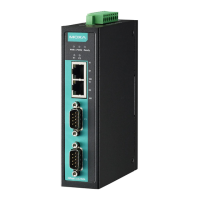
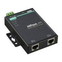
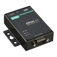
3. Hardware Introduction
The NPort IA5150A series has one RS-232 DB9 serial port and one
RS-422/485 terminal block for serial data communication. The
NPort IA5250A series has two RS-232/422/485 3-in-1 DB9 serial
ports for serial data communication. Each model has one 8-contact
screw-type terminal block, which is located on the top for power
input and relay output.
NPort IA5150A Series Appearance
Top View
Side View
Front View
DIN-Rail
PWR1 PWR2Ready
P1
E1
E2
10
100
100
10
P1RS-232
RS-422/485
Ethernet switch ports
RS-232 port
RS-422/485 port
LED indicators
NPort IA5150A
MOXA
Dual power inputs and relay output
Reset to default button
NPort IA5250A Series Appearance
Top View Side View
DIN-Rail
PWR1 PWR2Ready
P1
E1
E2
10
100
100
10
P1
Ethernet switch ports
RS-232/422/485 ports
LED indicators
NPort IA5250A
P2
MOXA
Dual power inputs and relay output
Reset to default button
Front View
The Reset to Default Button—Depress the Reset to default
button for 5 continuous seconds to load the factory default settings.
Use a pointed object, such as a straightened paper clip or toothpick,
to depress the Reset to default button. This will cause the Ready
LED to blink on and off. The factory default settings are loaded
once the Ready LED stops blinking (after about 5 seconds). At this
point, you can release the Reset to default button.
NPort IA5150A/IA5250A LED Indicators (front panel)
Name
off No data is being transmitted or received through
the serial port.
4. Hardware Installation Procedure
STEP 1: After removing the NPort IA5150A/IA5250A series from
the box, the first thing you should do is connect the power adaptor.
Connect the 12-48 VDC power line with the NPort IA5150A/
IA5250A series’ terminal block, or connect the DIN-Rail power
supply with the NPort IA5150A/IA5250A series’ terminal block.
STEP 2: Connect the NPort IA5150A/IA5250A series to a network.
Use a standard straight-through Ethernet cable to connect to a
Hub or Switch. When setting up or testing the NPort IA5150A/
IA5250A series, you might find it convenient to connect directly to
your computer’s Ethernet port. In this case, use a cross-over
Ethernet cable.
STEP 3: Connect the NPort IA5150A/IA5250A series’ serial port to
a serial device.
STEP 4: The NPort IA5150A/IA5250A series is designed to be
attached to a DIN-Rail or mounted on a wall. For DIN-Rail
mounting, push down the spring and properly attach it to the
DIN-Rail until it “snaps” into place. For wall mounting, install the
wall mount kit (optional) first, and then screw the device onto the
wall. The following figure illustrates the two mounting options:
Step1: Push down the spring
Step2: Click into DIN rail
Step1: Install Wall mount kit
Step2: Screw onto wall
DIN-Rail InstallationWall Mount Installation
– 1 –
– 2 – – 3 –