
S
Susan JohnsonAug 3, 2025
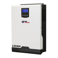
What to do if MPP Solar 2424LV-HS Inverter has no response after power on?
- RRobert BrownAug 3, 2025
If your MPP Solar Inverter doesn't respond after you power it on, it could be due to: * **Low Battery Voltage:** Check if the batteries and wiring are well connected. * **Reversed Battery Polarity:** Re-charge or replace the battery.