EasyManua.ls Logo

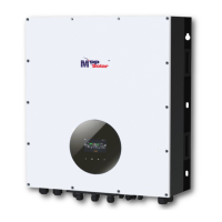
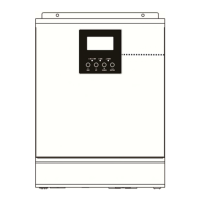
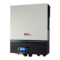
MPP Solar LV2424 User Manual

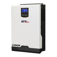
MPP Solar LV2424
50 pages
To Next Page IconTo Next Page
Page #1 background imageLoading...
Page #1 background image
Hybrid 1KW-5KW
INVERTER / CHARGER
Version: 1.1
User Manual

Questions and Answers:

MPP Solar LV2424 Specifications

General IconGeneral
ModelLV2424
Rated Power2400W
Nominal DC Input Voltage24V
Efficiency90%
Maximum Solar Charge Current80A
Max PV Input Power3000W
Transfer Time10ms
CoolingFan
Output Frequency50/60Hz
Battery TypeLead-acid or Lithium
CommunicationRS232 / USB

Summary

ABOUT THIS MANUAL

Purpose

Details the manual's objective regarding assembly, installation, operation, and troubleshooting of the unit for future reference.

Scope

Provides safety and installation guidelines, including information on tools and wiring for the inverter/charger.

SAFETY INSTRUCTIONS

Contains critical safety and operating instructions to be read and kept for future reference.

INTRODUCTION

Product Overview

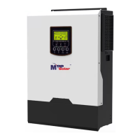
Illustrates and describes the components and functionality of the hybrid PV inverter system.

INSTALLATION

Unpacking and Inspection

Guides users through checking the unit and package contents for any damage before installation.

Preparation

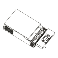
Details the necessary steps to prepare the unit for installation, involving cover removal.

Mounting the Unit

Provides guidelines on selecting an installation location, considering safety, visibility, and heat dissipation.

Battery Connection

Explains the procedure and requirements for safely connecting the battery to the inverter/charger.

AC Input/Output Connection

Details the correct method for connecting AC input power and output to the inverter/charger.

PV Connection

Outlines the process for connecting photovoltaic (PV) modules to the inverter, including module selection criteria.

Communication Connection

Instructs on connecting the inverter to a computer for monitoring software installation and usage.

Dry Contact Signal

Describes the function of the dry contact signal for external devices based on battery voltage levels.

OPERATION

Power ON/OFF

Explains how to turn the unit on and off after proper installation and battery connection.

Operation and Display Panel

Details the front panel components: indicators, function keys, and LCD display for monitoring status.

LCD Display Icons

Provides an explanation of various icons and digital displays on the LCD screen.

Mode operation information

Illustrates different operating modes and their corresponding LCD display indications.

LCD Setting

Guides users through accessing and configuring various operational parameters via the LCD interface.

Display Setting

Describes how to cycle through and view different operational data on the LCD display.

Operating Mode Description

Explains the behavior and LCD display of different operating modes like Standby, Line, and Battery modes.

Warning Indicator

Lists warning codes, their corresponding events, and how they are indicated on the unit.

Faults Reference Code

Provides a reference for fault codes, their descriptions, and the corresponding icons displayed on the unit.

PARALLEL FUNCTION (only for 2.4KW/3KW/4KW/5KW models)

Introduction

Introduces the inverter's capability for parallel operation in single, two-phase, and three-phase configurations.

Package Contents

Lists the items included in the parallel kit for setting up parallel operation.

Parallel board installation

Provides step-by-step instructions for installing the parallel board onto the inverter unit.

Mounting the Unit

Details the required spacing and mounting configuration for multiple inverters in parallel operation.

Wiring Connection

Specifies the recommended battery cable and terminal sizes for parallel inverter connections.

Parallel Operation in Single phase

Illustrates power and communication connections for parallel operation of two to nine inverters in single phase.

Support 2-phase equipment (only for 2.4KW model)

Details connection diagrams for supporting 2-phase equipment with the inverters.

Support 3-phase equipment

Provides connection diagrams for supporting 3-phase equipment with the inverters.

PV Connection

Refers to the single unit manual for PV connection and cautions about separate connections for each inverter.

LCD Setting and Display

Explains AC output modes for single, 2-phase, and 3-phase parallel operations via LCD settings.

Fault code display

Lists fault codes related to parallel operation, their events, and corresponding icons.

Commissioning

Details the steps for commissioning parallel systems in single-phase, two-phase, and three-phase configurations.

Related product manuals