32
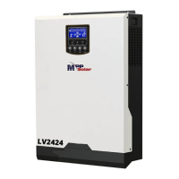
Step 7: Put communication board back to the unit.
Step 8: Put wire cover back to the unit. Now the inverter is providing parallel operation function.
4. Mounting the Unit
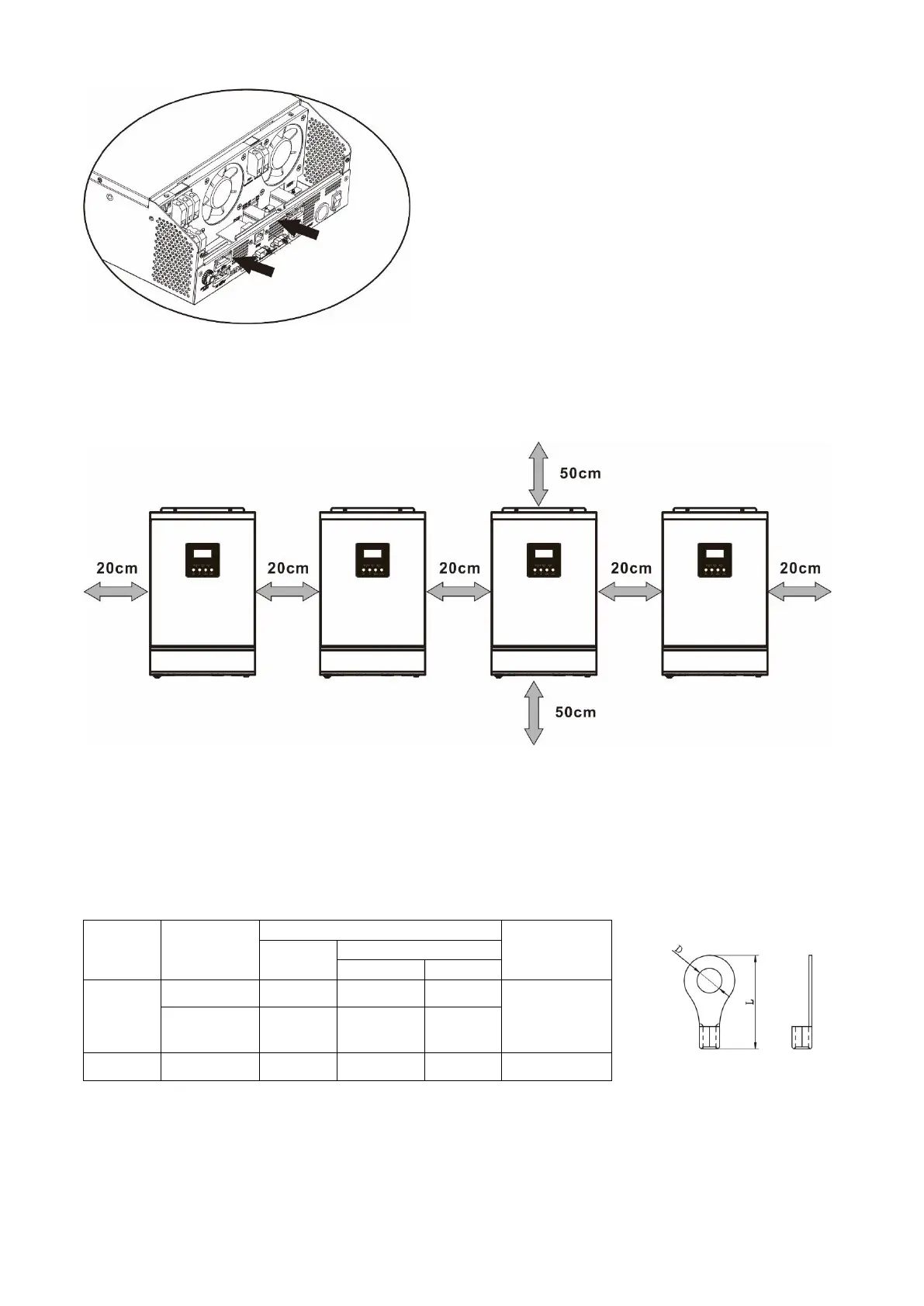
When installing multiple units, please follow below chart.
NOTE: For proper air circulation to dissipate heat, allow a clearance of approx. 20 cm to the side and approx.
50 cm above and below the unit. Be sure to install each unit in the same level.
5. Wiring Connection
The cable size of each inverter is shown as below:
Recommended battery cable and terminal size for each inverter:
WARNING: Be sure the length of all battery cables is the same. Otherwise, there will be voltage difference
between inverter and battery to cause parallel inverters not working.
 Loading...