3 Mounting
Maschinenfabrik Reinhausen 2013 92349487/01 EN TAPGUARD® 260
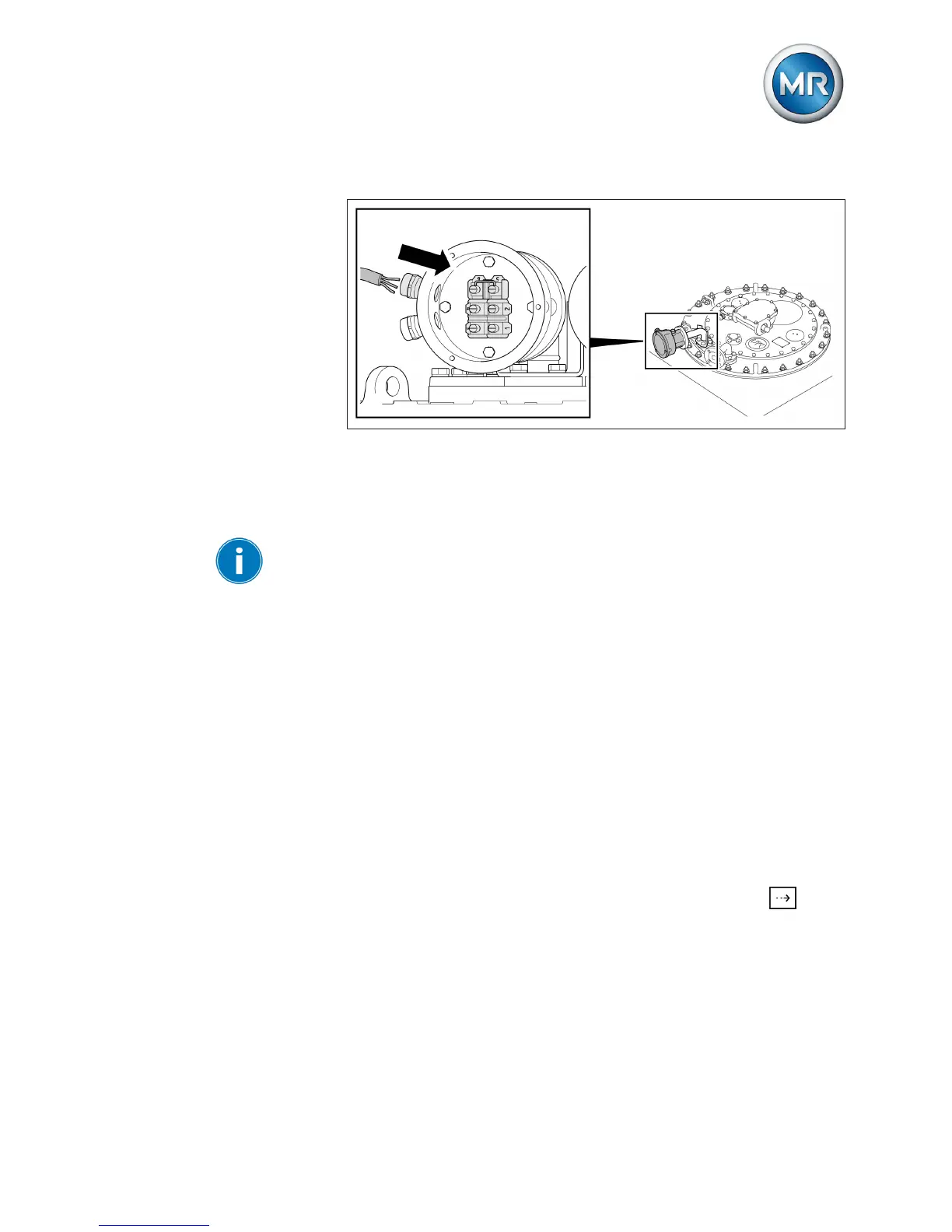
4. Insert connecting lead through terminal area into terminal box.
Figure 5: Connection of the tap-change supervisory control
5. Wire connecting lead in accordance with motor-drive unit's connection
diagram.
6. Fit terminal box cover.
When you close the temperature sensor cover, make sure that the seal is
correctly positioned and that no connecting leads are wedged in.
Connecting load current measurement
You have to perform the wiring for the load current measurement in accord-
ance with the connection diagram that came with the motor-drive unit. The
following signals can be wired:
▪ 4...20 mA (AD8 card)
▪ 0.2 A, 1 A or 5 A (MI card)
To connect the load current measurement, proceed as follows:
1. Wire load current measurement in accordance with motor-drive unit's
connection diagram.
2. Only with load current measurement via MI card: Remove short-circuit-
ing jumper (see connection diagram, terminals X1:255 and X1:256 in
standard version).
3. Check load current shown on device display by pressing the
key in
the main screen.
3.3
 Loading...