Do you have a question about the MR VACUTAP RMV-II and is the answer not in the manual?
Technical file applies to VACUTAP® RMV-II on-load tap-changer with standard position designations.
Information about the manufacturer, Reinhausen Manufacturing Inc., and contact details.
Technical file is incomplete without supporting documents like technical data and drawings.
Keep the technical file and supporting documents ready and accessible for future use.
Explains the display of warnings, signal words, and pictograms used in the technical file.
Explains the display of warnings, signal words, and pictograms used in the technical file.
Describes how information is laid out to simplify and improve understanding of procedures.
Explains the structure of single-step and multi-step instructions within the document.
Defines the intended use of the on-load tap-changer and conditions for safe operation.
Provides general safety guidelines covering personal protective equipment and work area safety.
Discusses limits on tap change operations and switching capacity to prevent injury and damage.
Emphasizes safe operation practices and regular checks of safety equipment.
Advises against working in areas with risk of explosion due to flammable gases or dusts.
Highlights the importance of observing and maintaining safety markings on the product.
Stresses the need to operate the product within specified ambient conditions.
Warns about using unapproved materials and specifies requirements for hoses and lubricants.
States that unauthorized changes can lead to injury or damage and require manufacturer consultation.
Warns against using unapproved spare parts, which can cause injury or damage.
Outlines requirements for electrically skilled and trained persons for safe operation.
Defines the operator's role and the need for training by the operating company.
Recommends using the manufacturer's Technical Service for maintenance, repairs, and retrofitting.
Mentions personnel trained by the manufacturer for special maintenance tasks.
Details necessary personal protective equipment for minimizing health risks.
Lists specific PPE like safety glasses, visor, hard hat, and hearing protection.
Details how the product is packaged and delivered, including its components.
Explains the function of RMV-II tap-changers in regulating voltage or phase angle.
Explains the function of RMV-II tap-changers in regulating voltage or phase angle.
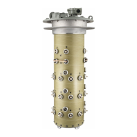
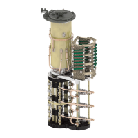
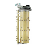
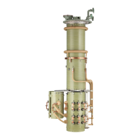
Describes the design and main components of the RMV-II on-load tap-changer.
Specifies the location of the on-load tap-changer's name plate.
Details the MPreC® pressure relief device, its function, and compliance with IEC standards.
Details the MPreC® pressure relief device, its function, and compliance with IEC standards.
Explains how the motor-drive unit adjusts the operating position of tap-changers.
Explains how the motor-drive unit adjusts the operating position of tap-changers.
Describes how the motor-drive unit handles voltage interruptions during tap-change operations.
Mentions that actual equipment may differ from illustrations.
Lists protective devices fitted within the motor-drive unit for safety.
Explains how the monitoring system detects vacuum interrupter malfunctions.
Explains how the monitoring system detects vacuum interrupter malfunctions.
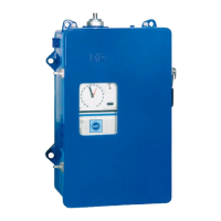
Details the indicators and controls of the monitoring system behind the motor-drive unit door.
Explains the function and components of the dehydrating breather.
Describes how products are packaged for protection against moisture and damage.
Details proper stacking and handling of crates to prevent property damage.
Explains the shipping pictograms used for safe transport and storage.
Provides instructions on recording and reporting external transport damage found upon receipt.
Provides instructions on recording and reporting external transport damage found upon receipt.
Outlines steps to take when transport damage is discovered after unpacking.
Instructions for unpacking and checking for damage, emphasizing secure handling.
Advises on proper storage procedures, including filling with oil and nitrogen.
Steps to perform before mounting the on-load tap-changer on the transformer.
Instructions for welding the oil compartment to the transformer tank, ensuring a proper seal.
Instructions for connecting the tap winding and on-load tap-changer take-off lead carefully.
Essential steps before fitting the motor-drive unit, including checking serial numbers and neutral position.
Details how to check the neutral position of the on-load tap-changer's change-over selector contacts.
Explains how to verify the neutral position of the motor-drive unit's tap position and tap-change indicators.
Differentiates between standard and offset assembly methods for the motor-drive unit.
Refers to external operating instructions for detailed fitting and electrical connection.
Step-by-step guide for manually checking the tap-changer's operation and component movement.
Verifies the correct functioning of the motor-drive unit and monitoring system.
Instructions for performing the transformer ratio test in all operating positions.
Instructions for performing the transformer ratio test in all operating positions.
Details on measuring DC resistance across various operating positions and permitted currents.
Detailed instructions and diagram for mounting the dehydrating breather.
Refers to relevant operating instructions for the pressure relief device.
Specifies checks required before initial transformer energization, referencing previous chapters.
Guides on testing tap change operations for mechanical functions after installation.
Instructions for performing high-voltage tests to ensure joint operation and identify malfunctions.
Steps for transporting the transformer with the motor-drive unit removed.
Checks the completeness and functionality of safety current circuits for the transformer and related equipment.
Tests tap change operations for mechanical functions after drying and filling with oil.
Procedures and precautions for energizing the transformer after installation.
Lists annual checks including oil quality, motor-drive unit, and return to starting position.
Details how to check dielectric strength and water content of the insulating oil annually.
Refers to motor-drive unit operating instructions for checking switching functions.
Steps to verify the on-load tap-changer returns to its starting position after an error.
Guidelines for trained experts to perform visual checks on the transformer and components.
General safety warnings and notes regarding fault elimination procedures.
A table assisting in detecting and remedying faults, with actions for various error patterns.
Details the displays and controls of the monitoring system (VIM) behind the motor-drive unit door.
Describes LED indications on the monitoring circuit board and swing frame for various operating statuses.
Specifies maintenance intervals and the importance of observing them to prevent damage.
Steps to safely take the on-load tap-changer out of service for maintenance.
Procedures for draining oil and testing its dielectric strength and water content.
How to check for any visible external damage on vacuum interrupters.
How to check for any visible external damage on vacuum interrupters.
How to check the contact erosion indicator for vacuum interrupter wear.
Information on replacing vacuum interrupters when excessive wear is detected.
How to check the condition of the by-pass switch contacts P₂ and P₃.
Specifies replacement of the braking contactor in the motor-drive unit after 500,000 operations.
Checks to perform on the monitoring system during maintenance.
Procedures for maintaining the dehydrating breather, including drying agent replacement.
Steps to prepare the on-load tap-changer for service after maintenance work.
Provides detailed technical specifications for the RMV-II (15 kV) on-load tap-changer.
Provides detailed technical specifications for the RMV-II (26.4 kV) on-load tap-changer.
Provides detailed technical specifications for the RMV-II (72.5 kV) on-load tap-changer.
Lists general parameters like design, tank dimensions, weight, and oil filling quantity.
Specifies the operating temperature range for the on-load tap-changer.
Provides limit values for dielectric strength and water content of the insulating oil.
| Brand | MR |
|---|---|
| Model | VACUTAP RMV-II |
| Category | Industrial Equipment |
| Language | English |