Home
MR
Industrial Equipment
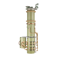
OILTAP R
MR OILTAP R - User Manual
206 pages
Manual
Specs
Ask a question
Save Page as PDF
To Next Page
To Next Page
Loading...
On-Load Tap-Changer
OILTAP® R
Installation and Commissioning Instructions
4427410/00 EN
2
Table of Contents
Main Page
Default Chapter
3
Table of Contents
3
1 Introduction
7
Validity
7
Manufacturer
7
Subject to Change Without Notice
7
Completeness
7
Safekeeping
8
Notation Conventions
8
Symbols
8
Hazard Communication System
9
Information System
11
2 Safety
12
General Safety Information
12
Appropriate Use
12
Inappropriate Use
13
Personnel Qualification
13
Operator's Duty of Care
13
Personal Protective Equipment
14
Protective Devices
15
Protective Relay RS
15
Pressure Monitoring Device
15
Rupture Disk
16
Pressure Relief Device Mprec
16
Tap-Change Supervisory Control
16
Temperature Monitoring
16
3 Product Description
17
Scope of Delivery
17
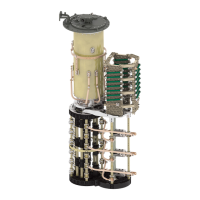
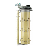
On-Load Tap-Changer
17
Function Description
17
Setup/Versions
18
Name Plate
20
Drive Shaft
21
Function Description
21
Setup/Models of Drive Shaft
21
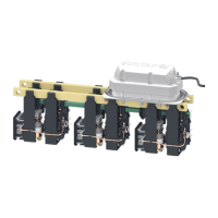
RS Protective Relay
24
Function Description
24
Setup/Models of Protective Relay
24
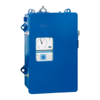
Pressure Monitoring Device DW
26
Function Description
26
Structure/Versions of the Pressure-Operated Relay
27
OF 100 Oil Filter Unit
29
4 Packaging, Transport and Storage
30
Packaging
30
Suitability
30
Markings
30
Transportation, Receipt and Handling of Shipments
31
Storage of Shipments
32
Unpacking Shipments and Checking for Transportation Damages
33
5 Mounting
34
Preparatory Work
34
Fitting Mounting Flange on Transformer Cover
35
Fitting Stud Bolts on Mounting Flange
35
Installing the Standard Version On-Load Tap-Changer in the Transformer
36
Fastening On-Load Tap-Changer to Transformer Cover
36
Connecting Tap Winding and On-Load Tap-Changer Take-Off Lead
44
Carrying out the Transformer Ratio Test
48
Measuring DC Resistance on Transformer
51
Drying On-Load Tap-Changer in Autoclave
51
Drying On-Load Tap-Changer in Transformer Tank
54
Installing the On-Load Tap-Changer in the Transformer (Bell-Type Tank Version)
67
Inserting On-Load Tap-Changer into Supporting Structure
67
Connecting Tap Winding and On-Load Tap-Changer Take-Off Lead
75
Carrying out the Transformer Ratio Test
78
Measuring DC Resistance on Transformer
81
Drying On-Load Tap-Changer in Autoclave
81
Removing On-Load Tap-Changer Head
84
Attaching Bell-Type Tank and Connecting On-Load Tap-Changer Head with On-Load Tap-Changer
90
Drying On-Load Tap-Changer in Transformer Tank
101
Filling the Oil Compartment of the On-Load Tap-Changer with Oil
115
Fitting Protective Devices and Drive Components
116
Connecting the Tap-Change Supervisory Control (if Installed)
116
Installing Protective Relay in Piping and Connecting
117
Installing and Connecting the Pressure-Operated Relay
128
Fitting Motor-Drive Unit
131
Fitting Bevel Gear
131
Fitting Drive Shaft
132
Centering On-Load Tap-Changer and Motor-Drive Unit
162
Installing Electrics for Motor-Drive Unit
162
6 Commissioning the On-Load Tap-Changer at the Transformer Manufacturer's Site
163
Bleeding On-Load Tap-Changer Head and Suction Pipe
163
Bleeding On-Load Tap-Changer Head
163
Bleeding Suction Pipe on Pipe Connection S
164
Grounding the On-Load Tap-Changer
164
Performing Tests on Motor-Drive Unit
165
Performing Trial Tap-Change Operations
165
High-Voltage Tests on the Transformer
166
7 Transporting Transformer to the Operating Site
168
Transport with Removed Drive
168
Transport with Oil Fill and Without Oil Conservator
168
Transport Without Oil Fill
169
Emptying Oil Compartment Via Pipe Connection S
169
8 Commissioning the Transformer at the Operating Site
171
Checking Motor-Drive Unit
171
Checking Protective Relay
172
Checking Protective Relay (RS 2001, 2001/V, 2001/H, 2001/E, 2001/5, 2001/R, 2003)
172
Checking Protective Relay (RS 2004)
172
Checking Pressure Monitoring Device
172
Filling the Oil Compartment of the On-Load Tap-Changer with Oil
173
Bleeding On-Load Tap-Changer Head and Suction Pipe
176
Bleeding On-Load Tap-Changer Head
176
Bleeding Suction Pipe on Pipe Connection S
178
Performing Trial Tap-Change Operations
178
Commissioning the Transformer
179
9 Fault Elimination
180
Tripping of the Protective Relay and Re-Commissioning the Transformer
182
Flap Valve in in SERVICE Position
183
Flap Valve in off Position
183
Re-Commissioning the Transformer
183
Tripping the Pressure-Operated Relay and Putting the Transformer Back into Operation
184
Sensor in the OPERATION Position
184
Sensor in the off Position
184
Re-Commissioning the Transformer
185
10 Technical Data
186
Technical Data for Protective Relay
186
Special Models of Protective Relay
187
Protective Relay with CO Change-Over Contact as Tripping Switch
187
Protective Relay with Several Dry-Reed Magnetic Switches
187
Technical Data for Pressure Monitoring Device
188
11 Appendix
189
Limit Values for Dielectric Strength and Water Content of On-Load Tap-Changer Oil
189
OILTAP® R, Installation Drawing for Selector Size C/D (896705)
190
OILTAP® R, Installation Drawing for Selector Size E (897873)
191
OILTAP® R, R I 2002/2003-C/D, R I 3003-C/D, Bridges for Parallel Connection of Selector Plane (896706)
192
OILTAP® R, R I 2002/2003-E, R I 3003-E, Bridges for Parallel Connection of Selector Plane (898713)
193
OILTAP® R, On-Load Tap-Changer Head (893899)
194
OILTAP® R, Flange for Pressure Relief Device (895168)
195
Tracing Template for On-Load Tap-Changer Head (890183)
196
OILTAP® R, Supporting Flange for Bell-Type Tank Installation up to Um=300 Kv (896762)
197
OILTAP® R, Supporting Flange for Bell-Type Tank Installation up to Um=362 Kv (725912)
198
OILTAP® R, Tap Selector Connection Contacts and Change-Over Selector Connection Contacts for Selector Size E (897868)
199
Lifting Traverse for Bell-Type Tank Installation (890180)
200
Socket Wrench for Kerosene Drain Plug (890182)
201
Bevel Gear CD 6400, Dimensional Drawing (892916)
202
Glossary
203
Need help?
Do you have a question about the MR OILTAP R and is the answer not in the manual?
Ask a question
MR OILTAP R Specifications
Print Specification
General
Application
Power transformers
Type
On-load tap-changer
Operating mechanism
Motor-drive unit
Material
copper
Size
Varies by model
Related product manuals
MR MESSKO MTRAB
124 pages
MR ECOTAP VPD I
98 pages
MR VACUTAP VRC I
236 pages
MR VACUTAP RMV-II
72 pages
MR VACUTAP VRC III
236 pages
MR VACUTAP VR Series
236 pages
MR TAPMOTION ED Series
64 pages
MR VACUTAP VV-Ex Series
68 pages
MR TAPMOTION ED 100-S/L
64 pages
MR VACUTAP VV III 250 D
68 pages
MR VACUTAP VV III 400 D
68 pages
MR VACUTAP VV III 250 Y/D
80 pages