Do you have a question about the MR VACUTAP and is the answer not in the manual?
Details about the manufacturer, Maschinenfabrik Reinhausen GmbH, and contact information.
Lists supporting documents considered essential for the completeness of the technical file.
Instructions on keeping the technical file and supporting documents accessible for future use.
Defines the intended use of the on-load tap-changer in electrical energy systems and facilities.
General safety instructions to prevent accidents, malfunctions, and damage.
Specifies the required qualifications for personnel involved in assembly, commissioning, and maintenance.
Details the necessary personal protective equipment for working with the product.
Explains the function of the on-load tap-changer in adjusting transformer transmission ratio.
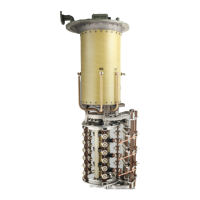
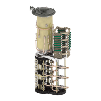
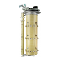
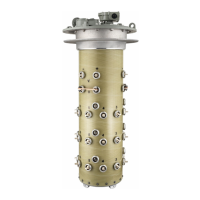
Details the main components and setup of the on-load tap-changer.
Describes the protective relay and pressure monitoring devices integrated with the tap-changer.
Details the design and different versions of the drive shaft system.
Steps for commissioning the transformer at the operating site.
Procedure for filling the on-load tap-changer oil compartment with fresh insulating fluid.
Instructions for checking the functionality of the protective relay before commissioning.
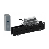
Guidelines and procedures for operating the motor-drive unit using the hand crank.
Actions to take when the protective relay trips, including re-commissioning.
Steps for addressing a trip from the pressure monitoring device and re-commissioning.
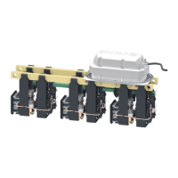
Detailed procedures for removing and installing the selector switch insert.
Scheduled visual checks for the tap-changer, motor-drive unit, and insulating fluid quality.
Specifies maintenance intervals based on switching operations.
Procedures for changing the insulating fluid, including emptying and filling.
Guidelines for performing DC resistance measurements on the transformer.
Electrical and mechanical data for the on-load tap-changer.
Environmental conditions for operation, transport, and storage.
Electrical data, switching capacity, and dielectric strength for the protective relay.
General technical data for the pressure monitoring device, including ambient conditions and pressure ranges.
Dimension drawing of the on-load tap-changer with upper gear unit.
Diagram showing installation details of the on-load tap-changer.
Assembly drawing for the bell-type mounting of the tap-changer.
Diagrams illustrating the swivel ranges of the upper gear unit.
| Brand | MR |
|---|---|
| Model | VACUTAP |
| Category | Industrial Equipment |
| Language | English |