3 Product description
Maschinenfabrik Reinhausen GmbH 202016 5788897/03 ENVACUTAP
®
VVS
®
4 Bevel gear 9 Oil conservator
5 Horizontal drive shaft 10 Active part
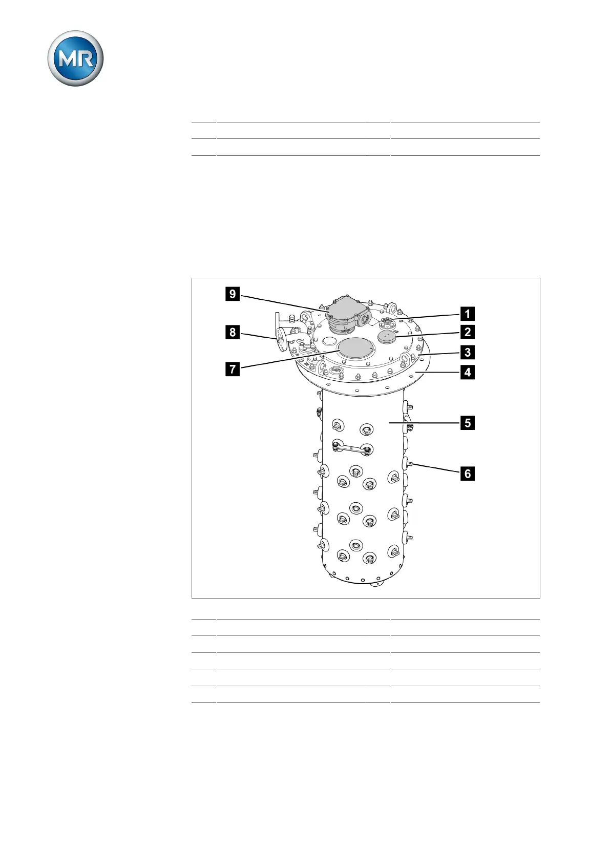
3.1.2 Setup/models
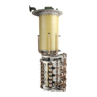
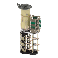
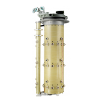
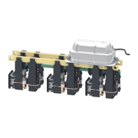
The following drawing shows the main components of the on-load tap-
changer.
You will find a detailed drawing of the on-load tap-changer in the "Drawings
[►Section 9, Page 82]" section.
Figure2: On-load tap-changer
1 Air-vent valve 2 Inspection window
3 On-load tap-changer head 4 Supporting flange
5 Oil compartment 6 Connection contact
7 Rupture disk 8 Pipe bend
9 Upper gear unit