6 Fault elimination
Maschinenfabrik Reinhausen GmbH 2020 435788897/03 EN VACUTAP
®
VVS
®
2. Contact and inform Maschinenfabrik Reinhausen of the following:
ð What was the load of the transformer at the instant of tripping?
ð Was there a tap-change operation on the on-load tap-changer immedi-
ately before or during the tripping?
ð Did any other protective devices of the transformer respond at the in-
stant of tripping?
ð Were switching operations in the network being carried out at the in-
stant of tripping?
ð Were overvoltages registered at the instant of tripping?
ð How high is the static pressure on the pressure relief device (height dif-
ference between the oil level in the on-load tap-changer oil conservator
and the pressure relief device)?
3. Take further action in agreement with Maschinenfabrik Reinhausen.
6.2.3 Re-commissioning the transformer
You can re-commission the transformer once the cause for tripping the pres-
sure monitoring device has been determined and resolved:
1. Ensure that the sensor on the snap-action switch is in the OPERATION
position.
2. Commission the transformer.
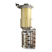
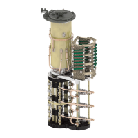
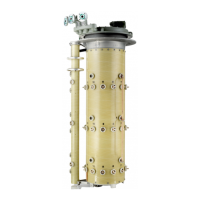
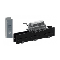
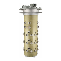
6.3 Removing/installing the selector switch insert
NOTICE
Damage to property!
Incorrectly performed work will damage the on-load tap-changer.
► Only staff trained by Maschinenfabrik Reinhausen GmbH may remove/in-
stall the selector switch insert.
► It is imperative that the assembly sequence described below be ob-
served.
► Prevent collisions between the selector switch insert and oil compartment
at all times.
If the on-load tap-changer column has to be removed and re-installed, pro-
ceed as follows.
6.3.1 Removing the selector switch insert
1. Move the on-load tap-changer to the adjustment position. The adjustment
position is indicated in the on-load tap-changer connection diagram.
2. When removing accessories, proceed in accordance with the relevant op-
erating instructions.
3. Ensure that the inspection window is sealed off with the cover.