1
Ultima MOS-5 Detector
Quick Start Guide
Mounting and Wiring
Tools Required
• “5mm” Allen head wrench to remove enclosure lid (included with gas detector).
• Flat-head screwdriver maximum 3/16 in (5 mm) width for terminal block (not included).
• Adjustable wrench for conduit or cable gland connections (not included).
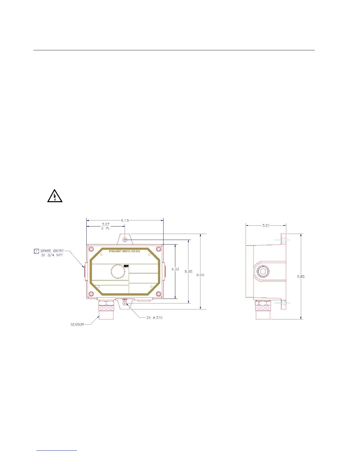
The outline and mounting dimensions for the Ultima MOS-5 Intelligent Sensor (Figure 1) should
be used when making installation determinations.
Information on Class I Division 1 and Zone 1 wiring methods can be found in the NEC and
CEC.
WARNING: Acetic acid will cause damage to metal components, metal hardware, ceramic
IC’s, etc. If damage results from the use of a sealant that outgases acetic acid
(RTV silicone), the warranty will be void.
Figure 1: Ultima MOS-5 Intelligent Sensor Outline and Mounting Dimensions, in inches
Terminal Connections
The terminal blocks (TB) are located inside the housing and can be accessed by removing the
cover. A label inside of the housing cover provides a diagram of all the terminal connections.
It is recommended that a minimum three-wire shielded cable be used for making the power and
0-20mA Output connection on TB2 of the Ultima MOS-5 Intelligent Sensor. It is also
recommended that separate two-wire shielded twisted pair cables be used for making the
Modbus connections. The spring type terminal block accepts 14 AWG to 20 AWG and the
 Loading...