INSTALLATION INSTRUCTIONS 3
AUTOTRONIC CONTROLS CORPORATION • 1490 HENRY BRENNAN DR., EL PASO, TEXAS 79936 • (915) 857-5200 • FAX (915) 857-3344
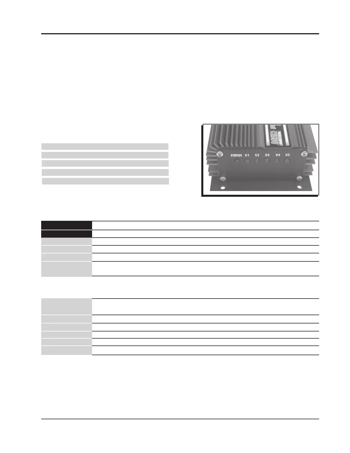
LEDs
There are six LED’s on the end panel of the Controller. The Red status LED will be on steady when
the unit is turned On. Once the launch reset wire is activated (Dark Blue) this LED will blink rapidly
(this is handy during clutch setup). When the launch reset wire is deactivated the status LED will
turn off.
The Green LEDs indicate the output status of each delay circut. The corresponding LED will light if
the output is On (ground).
If there is a shorted solenoid or an over heated solenoid driver the status LED will blink a fault code
to indicate which solenoid output is at fault. The fault codes will continue until the Launch Reset is
active or the power is turned off. The blink codes are:
Two blinks 1 output
Three blinks 2 output
Four blinks 3 output
Five blinks 4 output
Six blinks 5 output
WIRING
Figure 3 Status and Switch LEDS.
Heavy Red To Battery positive (+) or vehicle enable switch
Heavy Black To Battery negative or other good ground source
Violet To +12 volt ignition switch
Dark Blue Launch Reset input wire to +12 volts or ground
Light Blue Timer Control input wire to +12 volts momentary switch
Pink 12 volts output when the LaunchReset wire is active, 300 milliamp
load maximum - for suppling +12 volts to optional 2-step unit
5 Red wires These five Red wires can provide 12 volts to each circuit. They are fuse
protected (20 AMP).
Brown Supplies ground to activate switch 1
White Supplies ground to activate switch 2
Orange Supplies ground to activate switch 3
Yellow Supplies ground to activate switch 4
Dark Green Supplies ground to activate switch 5
OUTPUT ACTIVATION WIRES
 Loading...