2-22
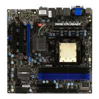
Hardware Setup
▍
MS-7576
BATT
+
SYSF
AN
3
CPUFA N1
PWR1
SYSF
AN
1
SYSF
AN
2
FDD1
JAUD 1
JCD1 JSP1
J139 4_1
PCI1
PCI2
PCI_E4
PCI_E1
PCI_E2
DIMM1
DIMM2
DIMM3
DIMM4
PCI_E3
RE SE T
CM OS
Cl r
JUSB 2 JU SB3
JCOM 1
JTPM
1
JFP1
JFP2
JUSB 1
SOCK ET AM3
SA
TA
4_5
IDE1
JPWR
1
SATA1
SA
TA
2_3
AMD
785G
AMD
SB710
Top:
Bott om:
LAN Jack
USB port s
Top: VGA port
Bott om:DVI port
Top:
Bott om:HDMI
USB port s
T:
M:
B:
Line -In
Line -Out
Mic
T:RS-O ut
M:CS -Out
B:SS -Out
T:1394 por t
M:
B:
USB port s
eSATA port
Top :
Bott om:
Keyb oard or Mouse
SPDI F
EZ OC Switch
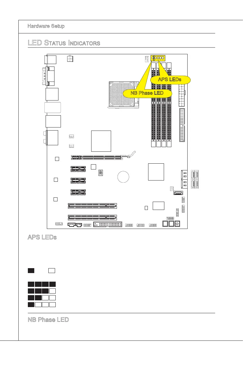
Led StatuS indicatorS
APS LEDs
These APS (Actve Phase Swtchng) LEDs ndcate the current CPU power phase
mode. Follow the nstructons
below to read.
: ON, : OFF
4 of the LEDs wll lght blue when CPU s n 4 phase power mode.
3 of the LEDs wll lght blue when CPU s n 3 phase power mode.
2 of the LEDs wll lght blue when CPU s n 2 phase power mode.
1 of the LEDs wll lght blue when CPU s n 1 phase power mode.
NB Phase LED
Lghts blue when the NB s operatng.
APS LEDs
NB Phase LED
 Loading...