MS-7267 Mainboard
2-14
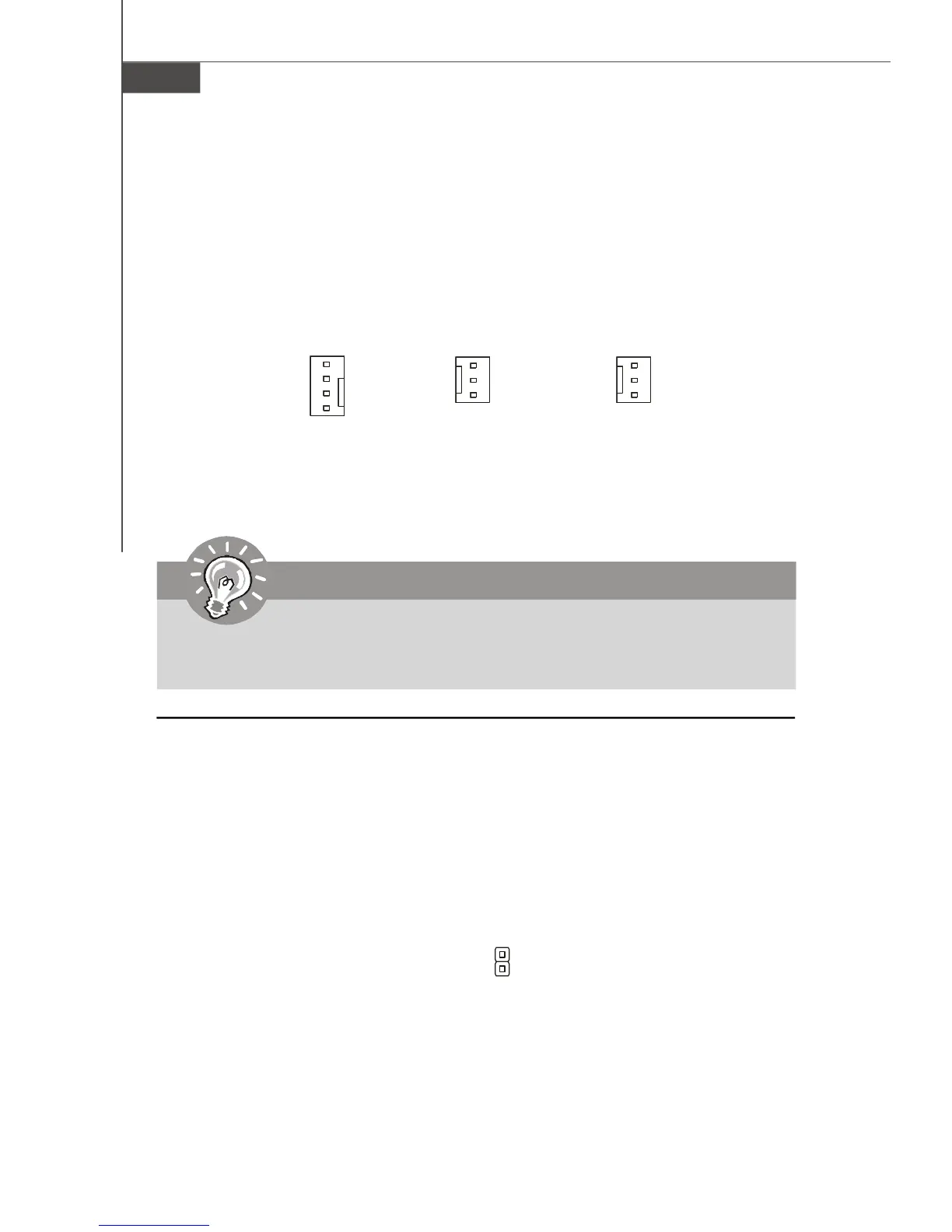
Fan Power Connectors: CPUFAN1, SYSFAN1 & PWRFAN1
The fan power connectors support system cooling fan with +12V. When connecting
the wire to the connectors, always take note that the red wire is the positive and
should be connected to the +12V, the black wire is Ground and should be connected
to GND. If the mainboard has a System Hardware Monitor chipset on-board, you must
use a specially designed fan with speed sensor to take advantage of the CPU fan
control.
SYSFAN1
NC
+12V
GND
+12V
GND
NC
PWRFAN1
Important
Please refer to the recommended CPU fans at Intel
®
official website or consult
the vendors for proper CPU cooling fan.
CPUFAN1
SENSOR
+12V
GND
CONTROL
Chassis Intrusion Switch Connector: JCI2
This connector connects to a 2-pin chassis switch. If the chassis is opened, the
switch will be short. The system will record this status and show a warning mes-
sage on the screen. To clear the warning, you must enter the BIOS utility and clear the
record.
JCI2
CINTRU
GND
1

 Loading...