Do you have a question about the MSI MS-98F5 and is the answer not in the manual?
Detailed specifications of the motherboard, including processor, memory, LAN, SATA, audio, graphics, and I/O.
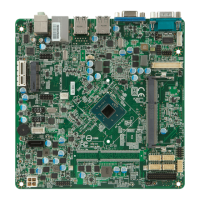
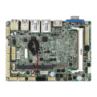
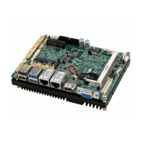
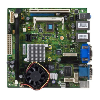
Visual diagram showing the physical placement and labeling of connectors and components on the motherboard.
Instructions for installing SO-DIMM memory modules into the motherboard slots.
Guide for connecting system and SATA power connectors to the motherboard.
Description of the rear panel connectors, including Serial, VGA, USB, and LAN ports.
Details on various onboard connectors like CPU fan, GPIO, SATA, front panel, LVDS, and USB.
Explains the function and settings for jumpers like Clear CMOS and AT/ATX Select.
Information on installing cards into PCIe and Mini-PCIe slots.
Instructions on how to access the BIOS Setup utility during system startup.
Overview of the BIOS menu bar and navigation keys for system configuration.
Configuration options for system date, time, and SATA mode.
Settings for NumLock state, logo display, ROM messages, and I/O configurations.
Options for managing boot device priorities and CSM support.
Configuration of administrator and user passwords, and chassis intrusion detection.
Settings related to DVMT pre-allocated memory and LCD panel type.
Controls for AC power loss recovery and Deep S5 power saving mode.
Options for saving changes, discarding them, restoring defaults, and exiting the setup.
Sample assembly code demonstrating the Watch Dog Timer (WDT) configuration.
Overview of the GPIO control tool provided for managing General Purpose Input/Output pins.
Sample assembly code for reading GPIO status and setting GPO output.
| Model | MS-98F5 |
|---|---|
| Form Factor | Mini-ITX |
| Socket | LGA 1151 |
| Memory Type | DDR4 |
| Memory Slots | 2 |
| Max Memory Support | 32 GB |
| Audio | Realtek ALC887 |
| PCI Express Slots | 1 x PCIe 3.0 x16 |
| USB Ports | 6 x USB 2.0 |
| LAN | Realtek 8111H Gigabit LAN |
| Video Outputs | HDMI, DisplayPort, VGA |
| Storage Interfaces | 4 x SATA 6Gb/s, 1 x M.2 |