1
< 1> Contents
Contents
Safety Information ........................................................................................... 2
Specifications ...................................................................................................3
Rear I/O Panel .................................................................................................6
LAN Port LED Status Table ................................................................................6
Overview of Components ................................................................................7
CPU Socket .........................................................................................................8
DIMM Slots .........................................................................................................9
PCI_E1~E3: PCIe Expansion Slot .......................................................................9
SATA1~6: SATA 6Gb/s Connectors ...................................................................10
M2_1: M.2 Slot (Key M) .....................................................................................10
ATX_PWR1, CPU_PWR1: Power Connectors ...................................................11
JCOM1: Serial Port Connector .........................................................................11
JFP1, JFP2: Front Panel Connectors ...............................................................12
JUSB1~2: USB 2.0 Connectors ........................................................................12
JUSB3: USB 3.1 Gen1 Connector .....................................................................13
JAUD1: Front Audio Connector ........................................................................13
CPU_FAN1, SYS_FAN1: Fan Connectors .........................................................14
JCI1: Chassis Intrusion Connector ..................................................................15
JBAT1: Clear CMOS (Reset BIOS) Jumper .......................................................15
EZ Debug LED: Debug LED indicators ............................................................15
BIOS Setup ..................................................................................................... 16
Entering BIOS Setup.........................................................................................16
Resetting BIOS .................................................................................................17
Updating BIOS ..................................................................................................17
Software Description .....................................................................................18
Installing Windows
®
7/ 8.1/ 10 .........................................................................18
Installing Drivers ..............................................................................................18
Installing Utilities .............................................................................................18
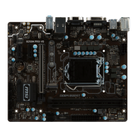
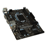
Thank you for purchasing the MSI
®
B250M PRO OPT BOOST
motherboard. This User Guide gives information about board
layout, component overview and BIOS setup.