EasyManuals Logo

MSI B650M PROJECT ZERO User Manual

MSI B650M PROJECT ZERO
428 pages
To Next Page IconTo Next Page
To Previous Page IconTo Previous Page
Page #90 background imageLoading...
Page #90 background image
36
Wichtig
Stellen Sie sicher, dass alle Anschlüsse mit den richtigen Anschlüssen des Netzteils
verbunden sind, um einen stabilen Betrieb der Hauptplatine sicherzustellen
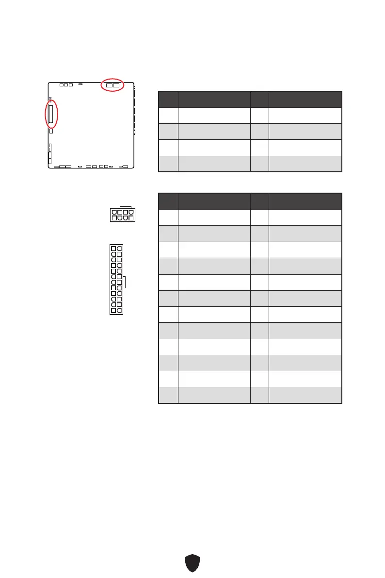
CPU_PWR1~2, ATX_PWR1: Stromanschlüsse
Mit diesen Anschlüssen verbinden Sie die ATX Stromstecker.
CPU_PWR1~2
Pin Signalname Pin Signalname
1 Ground 2 Ground
3 Ground 4 Ground
5 +12V 6 +12V
7 +12V 8 +12V
ATX_PWR1
Pin Signalname Pin Signalname
1 +3,3V 2 +3,3V
3 Ground 4 +5V
5 Ground 6 +5V
7 Ground 8 PWR OK
9 5VSB 10 +12V
11 +12V 12 +3,3V
13 +3,3V 14 -12V
15 Ground 16 PS-ON#
17 Ground 18 Ground
19 Ground 20 Res
21 +5V 22 +5V
23 +5V 24 Ground
5
4 1
8
CPU_PWR1~2
24
131
12
ATX_PWR1

Table of Contents

Questions and Answers:

Question and Answer IconNeed help?

Do you have a question about the MSI B650M PROJECT ZERO and is the answer not in the manual?

MSI B650M PROJECT ZERO Specifications

General IconGeneral
ChipsetAMD B650
Memory SupportDDR5
Maximum Memory Supported192GB
Form FactorMicro ATX
SocketAM5
Memory Slots4
Storage Interface4 x SATA 6Gb/s
Network2.5G LAN
AudioRealtek ALC897

Related product manuals