14
Rear I/O Panel
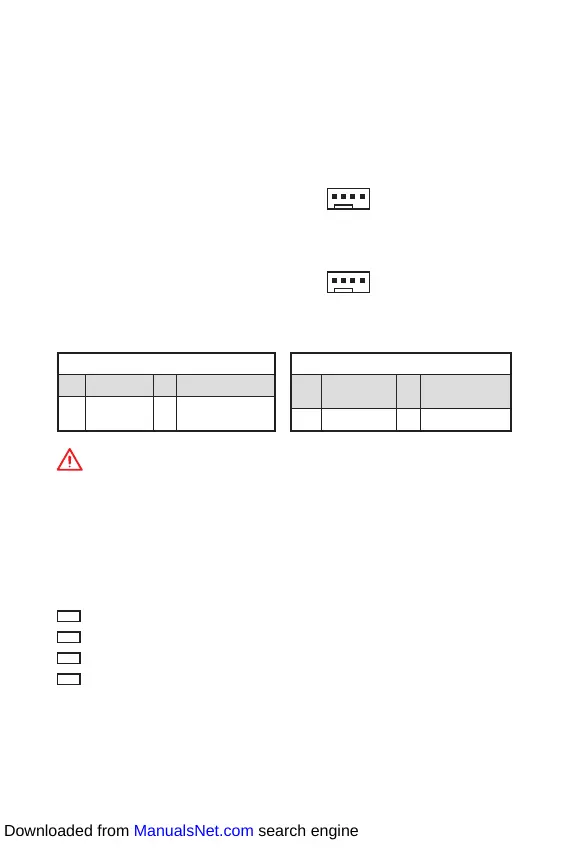
CPU_FAN1, SYS_FAN1: Fan Connectors
Fan connectors can be classified as PWM (Pulse Width Modulation) Mode or DC
Mode. PWM Mode fan connectors provide constant 12V output and adjust fan speed
with speed control signal. DC Mode fan connectors control fan speed by changing
voltage. When you plug a 3-pin (Non-PWM) fan to a fan connector in PWM mode, the
fan speed will always maintain at 100%, which might create a lot of noise. You can
follow the instruction below to adjust the fan connector to PWM or DC Mode.
PWM Mode pin definition
1 Ground 2 +12V
3 Sense 4
Speed Control
Signal
DC Mode pin definition
1 Ground 2
Voltage
Control
3 Sense 4 NC
Default PWM Mode fan connectors
Default DC Mode fan connectors
Important
y
You can switch between PWM mode and DC mode and adjust fan speed in BIOS >
HARDWARE MONITOR.
y
Make sure fans are working properly after switching the PWM/ DC mode.
1
CPU_FAN1
1
SYS_FAN1
Pin definition of fan connectors
EZ Debug LED
These LEDs indicate the status of the motherboard.
CPU - indicates CPU is not detected or fail.
DRAM - indicates DRAM is not detected or fail.
VGA - indicates GPU is not detected or fail.
BOOT - indicates booting device is not detected or fail.
Downloaded from ManualsNet.com search engine
 Loading...