EasyManua.ls Logo

MSI K8N Neo-V2 User Manual

MSI K8N Neo-V2
90 pages
To Next Page IconTo Next Page
Page #1 background imageLoading...
Page #1 background image
i
FCC-B Radio Frequency Interference Statement
This equipment has been tested and found to comply with the limits for a class B digital device, pursuant
to part 15 of the FCC rules. These limits are designed to provide reasonable protection against harmful
interference in a residential installation. This equipment generates, uses and can radiate radio frequency
energy and, if not installed and used in accordance with the instruction manual, may cause harmful
interference to radio communications. However, there is no guarantee that interference will occur in a
particular installation. If this equipment does cause harmful interference to radio or television reception,
which can be determined by turning the equipment off and on, the user is encouraged to try to correct the
interference by one or more of the measures listed below.
4 Reorient or relocate the receiving antenna.
4 Increase the separation between the equipment and receiver.
4 Connect the equipment into an outlet on a circuit different from that to which the receiver is
connected.
4 Consult the dealer or an experienced radio/ television technician for help.
Notice 1
The changes or modifications not expressly approved by the party responsible for compliance could void
the users authority to operate the equipment.
Notice 2
Shielded interface cables and A.C. power cord, if any, must be used in order to comply with the emission
limits.
VOIR LA NOTICE DNSTALLATION AVANT DE RACCORDER AU RESEAU.
Micro-Star International
MS-7030
This device complies with Part 15 of the FCC Rules. Operation is subject to the following two conditions:
(1) this device may not cause harmful interference, and
(2) this device must accept any interference received, including interference that may cause undesired
operation
G52-M7030XE
Question and Answer IconNeed help?

Do you have a question about the MSI K8N Neo-V2 and is the answer not in the manual?

MSI K8N Neo-V2 Specifications

General IconGeneral
Form FactorATX
CPU Socket TypeSocket 754
ChipsetNVIDIA nForce3 250
Supported CPUsAMD Athlon 64 / Sempron
Memory Slots3
Memory TypeDDR SDRAM
Max Memory3 GB
IDE2
Audio ChipsetRealtek ALC850
LAN Speed10/100 Mbps
PS/22
AGP Slots0
SATA4
USB Ports8
Audio Channels6
PCI Slots5 x PCI

Summary

FCC-B Radio Frequency Interference Statement

Notice 1

Advisory on modifications voiding user authority to operate the equipment.

Notice 2

Requirement for shielded interface cables and A.C. power cord for emission limits.

Copyright Notice

Trademarks

Revision History

Safety Instructions

WEEE Statement

Introduction

Layout

Specifications

CPU

Details on supported AMD K8 Athlon64 processors and clock speeds.

Chipset

Information on the NVIDIA nForce3 250 chipset features and capabilities.

Main Memory

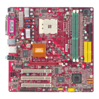
Specifications for DDR DIMM slots, maximum memory, and supported speeds.

Slots

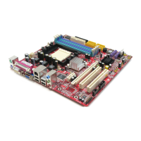
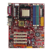
Details on AGP and PCI bus slots, including interface specifications.

On-Board IDE

Features of the IDE controller, operation modes, and device capacity.

On-Board Peripherals

List of integrated peripherals: floppy, serial, parallel, USB, and IrDA.

Audio

Details on the 6-channel software audio codec and compliance standards.

LAN

Information on the Realtek LAN controller and supported speeds.

BIOS

Overview of BIOS features like Plug & Play and DMI for system management.

NV RAID (Software)

Details on NV RAID support, RAID levels, and OS compatibility.

Dimension

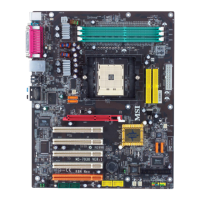
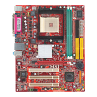
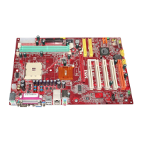
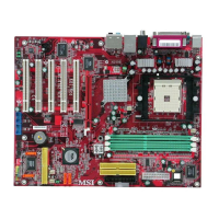
Specifications for the motherboard's ATX form factor dimensions.

Mounting

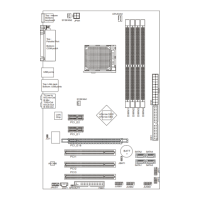
Information on the number of mounting holes for installation.

Rear Panel

Hardware Setup

Central Processing Unit: CPU

Guidance on installing the AMD Athlon64 processor and ensuring cooling.

CPU Installation Procedures for Socket 754

Step-by-step guide for safely installing the CPU into Socket-754.

Installing AMD Athlon64 CPU Cooler Set

Instructions for mounting the CPU cooler assembly onto the motherboard.

Memory

Information on the motherboard's DDR memory sockets and supported capacity.

Installing DDR Modules

Step-by-step guide for inserting DDR DIMM modules into the memory slots.

Power Supply

ATX 20-Pin Power Connector: JWR1

Instructions for connecting the ATX power supply to the 20-pin connector.

ATX 12V Power Connector: JPW1

Purpose and connection of the 12V power connector for the CPU.

Floppy Disk Drive Connector: FDD1

Description of the floppy disk drive connector and supported media types.

CD-In Connector: JCD1

Connector for CD-ROM audio input to the sound card.

Fan Power Connectors: C_FAN1/S_FAN1/S_FAN2/NB_FAN1

Details on connecting CPU, system, and chipset fans to the motherboard.

IDE Connectors: IDE1/IDE2

Information on IDE controllers, modes, and connecting drives.

Front Panel Connectors: JFP1/JFP2

Connectors for front panel switches, LEDs, and compliance standards.

Front Panel Audio Connector: JAUD1

Connector for front panel audio, compliant with Intel Front Panel I/O Guide.

Front USB Connector: JUSB1/JUSB2

Details on front USB 2.0 headers and high-speed data transfer capabilities.

Serial ATA HDD Connectors: SATA1/SATA2

Information on Serial ATA ports, data rates, and compliance.

Serial Port Connector: JCOM1 (optional)

Header for connecting secondary serial devices to the motherboard.

IrDA Infrared Module Header: JIR1

Connector for IrDA Infrared modules, requiring BIOS setup.

Chassis Intrusion Switch Connector: JCASE1

Connector for chassis intrusion switch and BIOS status reporting.

Clear CMOS Jumper: JBAT1

AGP (Accelerated Graphics Port) Slot

PCI (Peripheral Component Interconnect) Slots

PCI Interrupt Request Routing

BIOS Setup

Main Page

Overview of the AwardBIOS CMOS Setup Utility main menu and available options.

Cell Menu

Menu for CPU/DDR clock, timing, and overclocking settings for performance tuning.

Related product manuals